 Steve Pomeroy
For any project with multiple components, you need to start somewhere. Inspired by this awesome video from Look Mum No Computer, I decided to kick-off my modular synth project by building a voltage-controlled oscillator module.
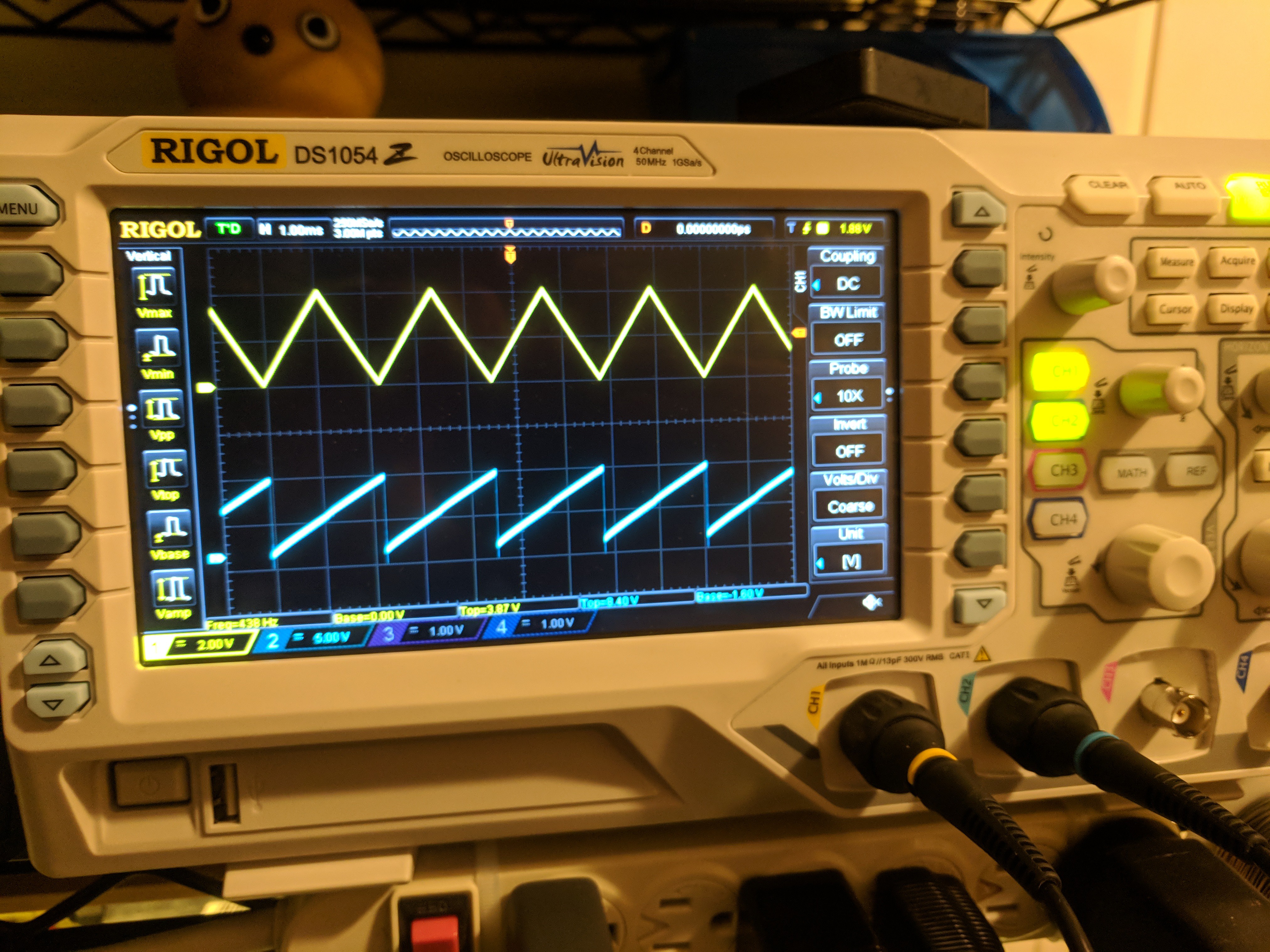
The voltage-controlled oscillator is the heart of any synthesizer: it's the bit that makes the source waveforms that you'll be tweaking and fiddling with. The inputs/outputs to a VCO are simple: just a single input control voltage and frequency-modulated waveforms for your output. Many VCO designs use 1V/octave, so I wanted to use that too.
The design that Look Mum No Computer made uses the CEM3340 chip, which has been used on many classic analog synthesizers. The CEM3340 has three waveform outputs: triangle, sawtooth, and square wave. It has a number of other nice features like temperature compensation and some stuff I don't yet fully understand involving waveform synchronization. It looked pretty easy to wire up, so I figured that'd be a great first step.
Because I figured I'd fry one, I opted to get one of the clones of the CEM3340 instead of the genuine thing (which is rather spendy): the AS3340. My fears were founded: I managed to plug in my power cord backwards the first time I powered on my board and fried both the op amp and the AS3340. Thankfully I bought 3.
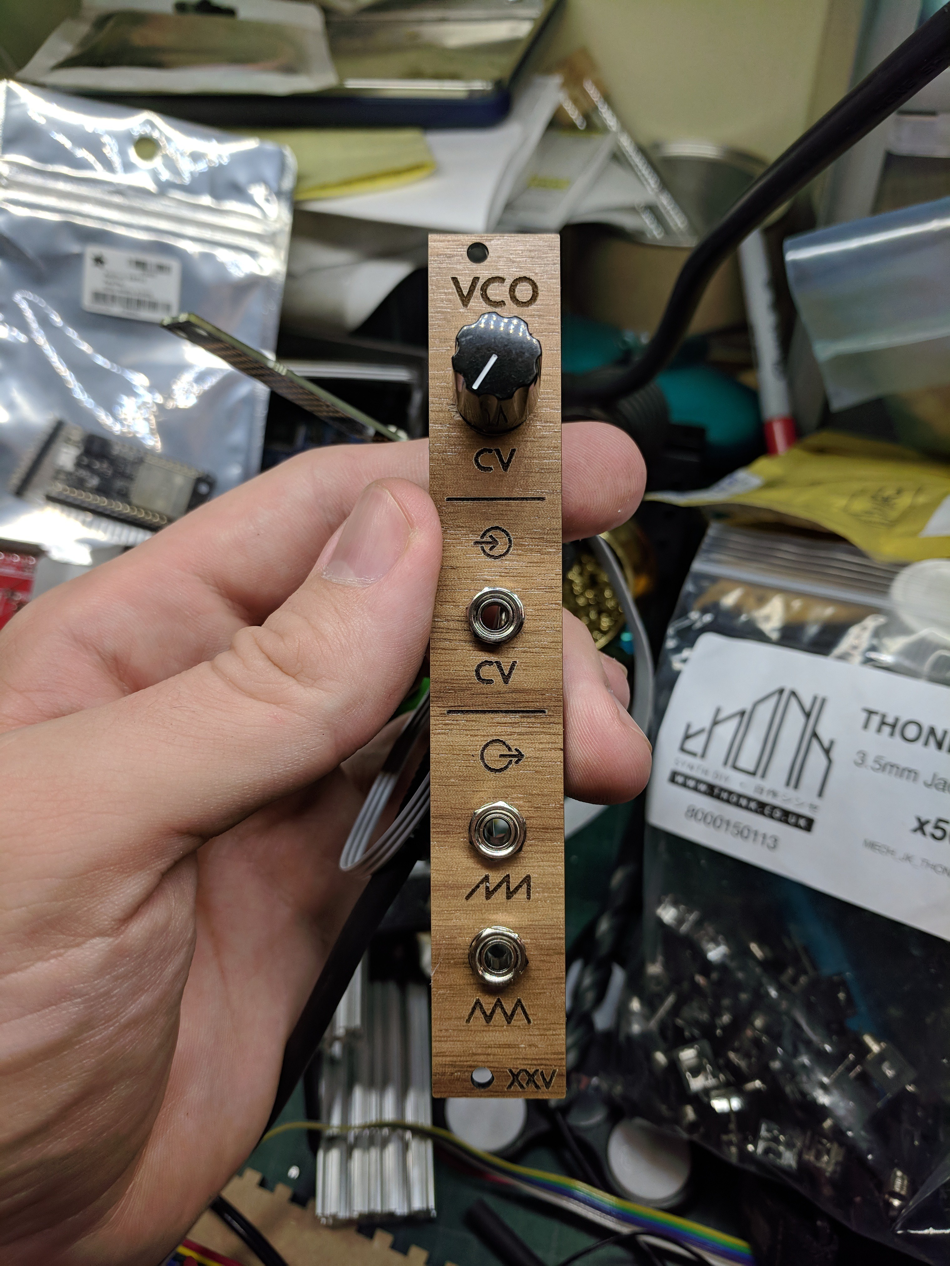
My initial design was copied directly from Look Mum's design, though adjusted for eurorack standards (1/8" jacks), a laid out PCB instead of stripboard, and to use all surface mount parts where possible. That design is shown in this post.
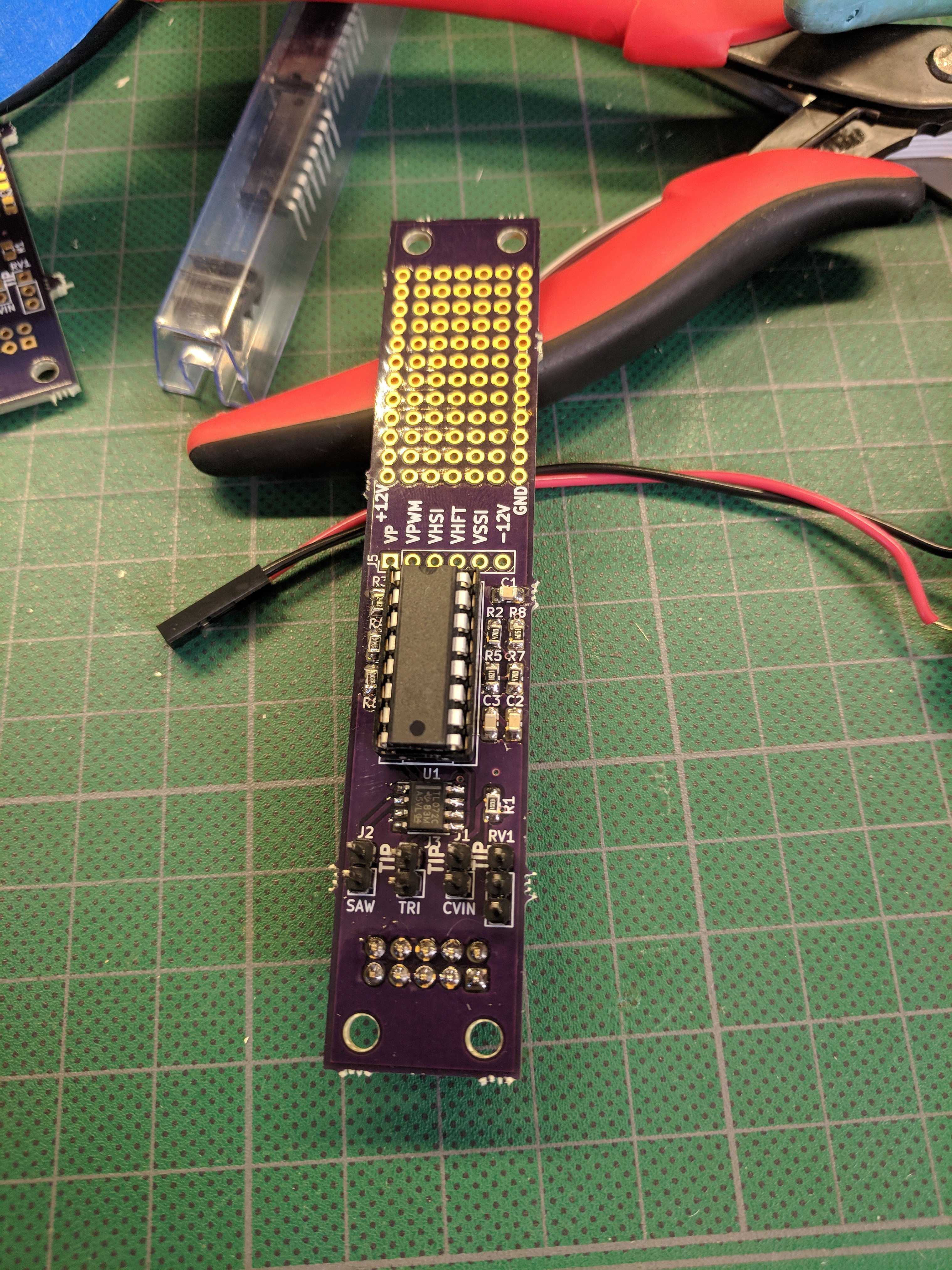
All the files for this design are available on in the VCO module repository, but I'm in the process of tweaking it so that I'll have a separate board for the pots and jacks instead of pigtail wiring them to the panel. This should help improve the front panel's rigidity plus make it easier to assemble.
Additionally, I'd like to build on Look Mum's design a bit and add that missing square wave output. It requires a 0-5V input to control pulse-width and I think that could either be another CV input or a knob (or both if there's room!). Although it's a small change, making this change is my first real challenge in my quest to learn analog electronics. It's a lot of fun studying the design of classic synths to try to understand why they chose the inputs/outputs they did for this chip.
Discussions
Become a Hackaday.io Member
Create an account to leave a comment. Already have an account? Log In.