 Gonçalo Nespral
What it can do:
This radio telescope takes pictures in radio (on frequencies between 10.7Ghz and 12.75GHz). Theoretically, this radio telescope should be able to take pictures of the sky, in radio. If the dish is aimed properly, the results should create an image of TV satellites orbiting the earth (those in geostationary orbit - they are always in the same position in the sky since they orbit the earth at the same speed at which it rotates). However, due to limitations caused by the small size of the dish, I won't be able to do any real radio astronomy with this (with a bigger dish, we can listen to lower frequencies (due to their longer wavelength) and a larger dish would also provide increased aperture which means more gain and smaller beamwidth (so higher resolution images too) . For example, by using a 1m dish, I would be able to listen to the hydrogen line. This is a spectral line (around 1420MHz) caused by the change in energy state of hydrogen atoms. Considering hydrogen is the most abundant element in the universe, and there are huge clouds of hydrogen everywhere in our galaxy, if I applied the same imaging technique (read How it works, below), I would be able to see the centre of the Milky Way (or at least receive a faint signal at 1420MHz). Now this is pretty cool, but very difficult to achieve.
How it works:
The idea is to have a motorised satellite dish, which can be controlled by a Raspberry Pi. The code on the Pi points the dish in a certain direction, and measures the intensity of the radio signal being received. This intensity and the position of the dish are then stored in a database. This is done many times as the radio telescope moves around and scans its surroundings. Each value for the intensity of the signal (with its associated dish position) are converted to pixels in the final image: the intensity of the signal being the brightness of the pixel, and the position of the dish being the location of the pixel on the final image. The output is a low resolution image, which represents the intensity of signals being received from different areas in the telescope's surroundings. Here is a video of my first scan:
Moving the dish:
I used 3D printed parts I designed to build each axis to move the dish. What I built is essentially and alt-azimuth mount for the satellite dish.
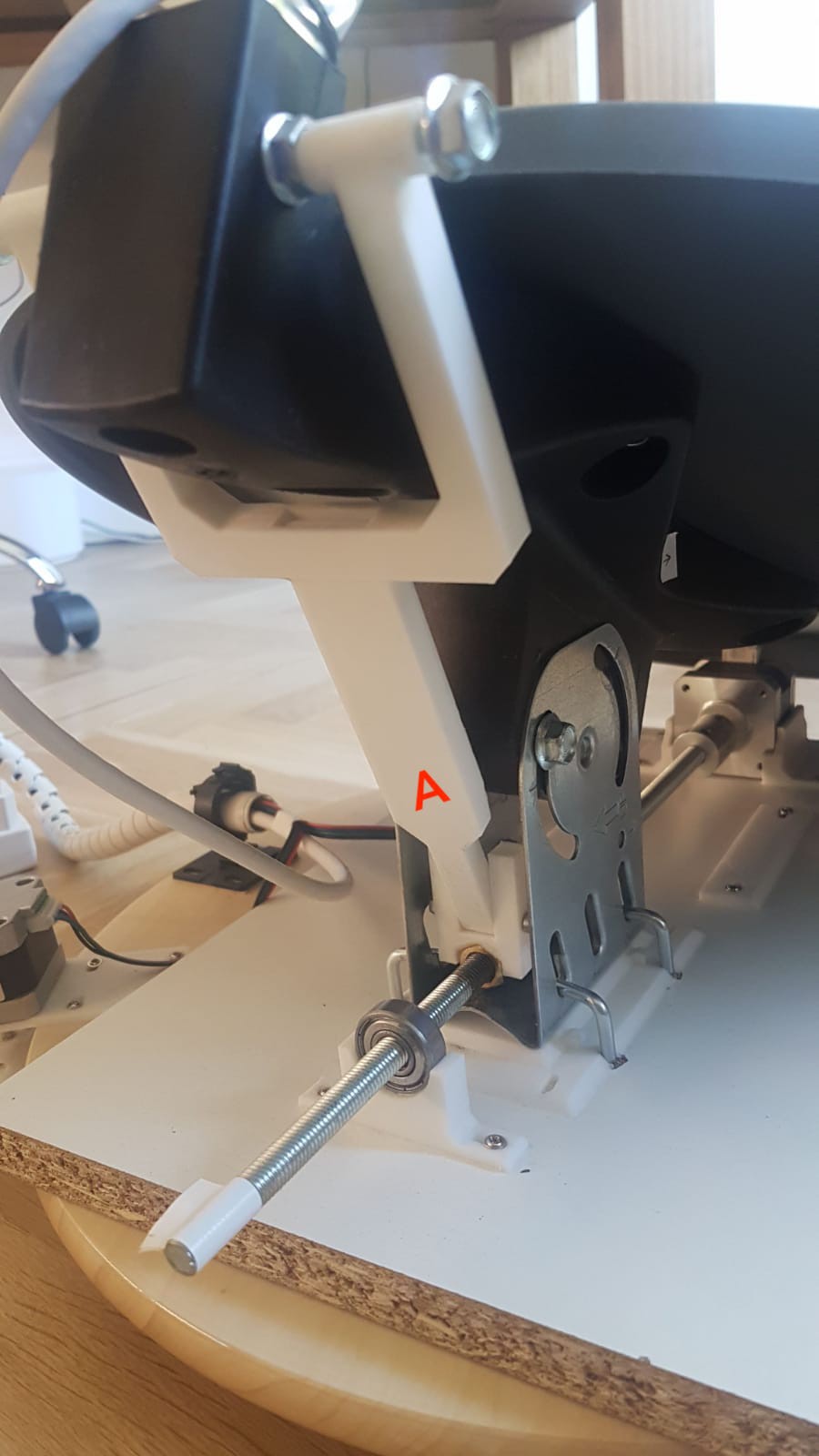
For the altitude axis, (up and down) I attached a stepper motor to a threaded rod using a flexible coupling. On the threaded rod I placed a nut, which, as the threaded rod rotates, moves forwards and backwards. Part A (below) is a 3D printed piece which then translates the horizontal motion of the nut into a vertical motion, to move the dish up and down, by pulling it and pushing it. I found that this method worked really well since it allowed for a decent amount of torque, and for precise, small movements. However, I was only able to point the dish between 0° and 50°(altitude), but with a few modifications i'm sure i could fix this.
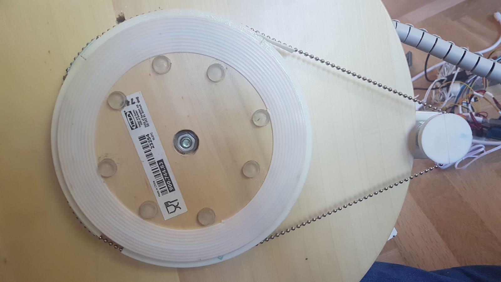
For the azimuth axis, (left and right) I ran a ball chain around a 3D printed adapter for the stepper motor, and around the base for the Lazy Susan. As the stepper motor rotates, the top plate of the Lazy Susan will also rotate, moving the dish, which is mounted on top of it. I had a few problems with this design, since the stepper motor had a little trouble rotating because of the weight of all the parts mounted on the turntable, but I managed to make it work in the end.
Receiving the signal on the Raspberry Pi:
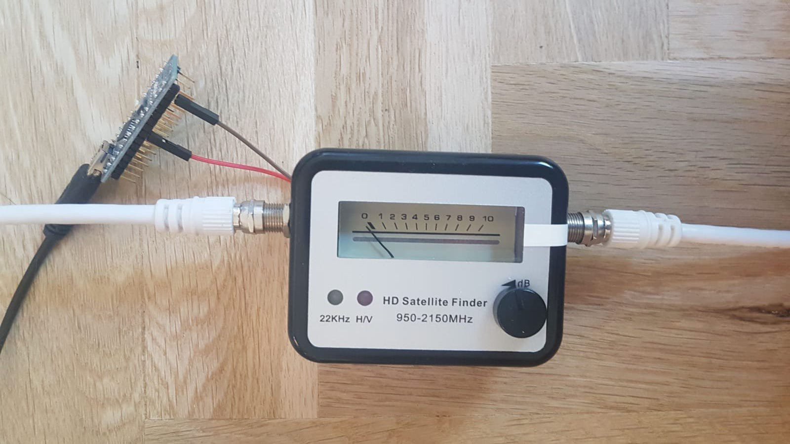
For the Raspberry Pi to be able to measure the power of the signal being received, I used a satellite finder. These are devices used to align antennas after they are installed. They are usually built with a buzzer, which changes pitch depending on the amount of signal being received. For my project, I removed the buzzer and soldered two wires onto the pads where the buzzer used to be:
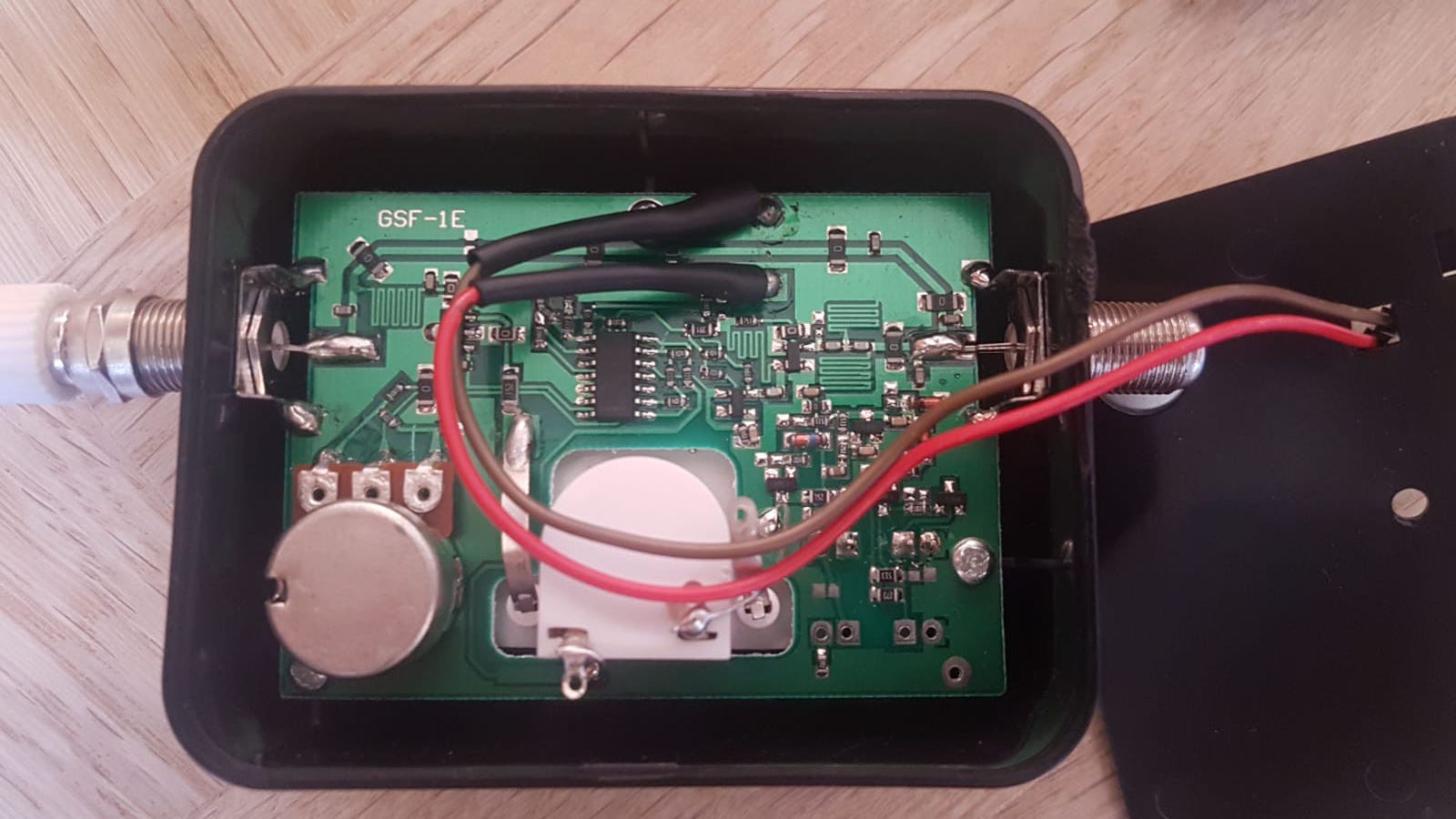
The current on these two wires (when the device is operating) is directly proportional to the amount of signal received. To measure the current I attached the wires to the analog input of an Arduino Nano (I used the Arduino because it has an analog input, which the RPi doesn't, and I didn't feel like using an analog to digital converter for the pi). I wrote a simple sketch on the Arduino which would read the signal, average it, and then send it to the raspberry pi over USB.
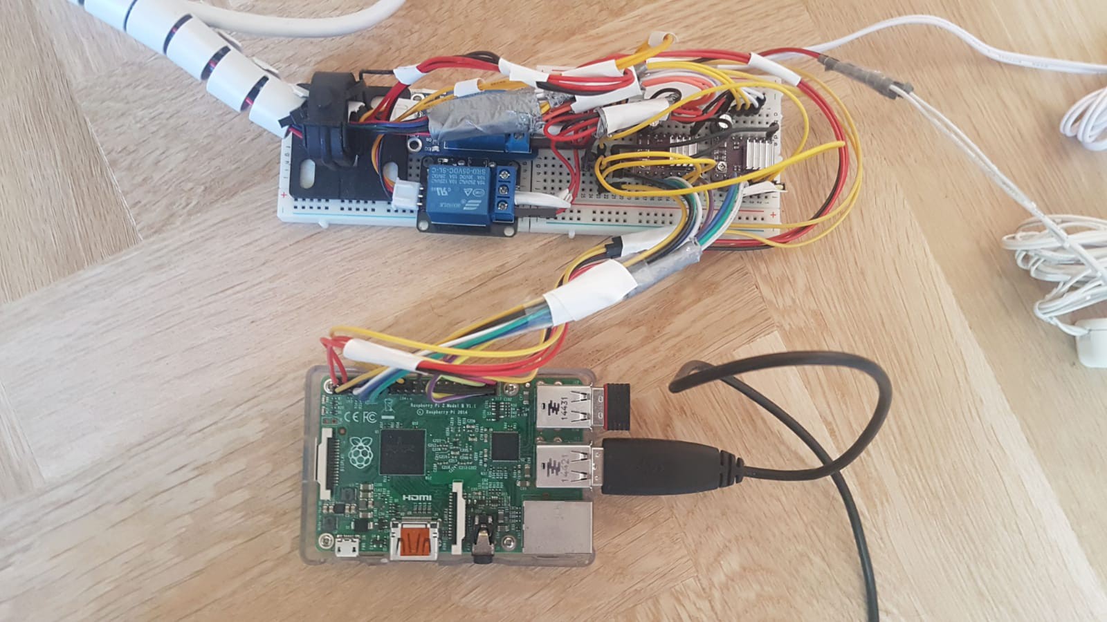
Everything wired up...
Yes, I know this setup is a bit of a mess... but it works. The two relays you can see in the picture below are attached to each of the power supplies for the stepper motors. This was done to prevent the stepper motors overheating by holding their position when they really didn't have to (for example, when the dish is scanning horizontally on a certain altitude, the altitude doesn't change so that stepper motor isn't needed, and its power is cut off. When the horizontal scan stops and the altitude has to be changed again, the power is switched back on).
Results:
After my first test (video at the top of the page), I was able to take an image of the wall in my room. It may not look like much but its a picture in radio. To me, this is actually super cool.

(Anybody know what those lines are?) Apparently thats stuff inside the wall in my room, but im not sure.
I then tested the radio telescope outside, but I wasn't able to get any good results. I'm still trying to figure out what went wrong. When I fix the problem I will post the results here.
I consider this project more of an experiment, to see what can be done with a relatively low cost (and tiny) radio telescope. Even though the results aren't great, I learned a lot as I worked on this project (about radio astronomy (and radio in general), how to use the Raspberry Pi to communicate with sensors and motors, and how to design my own 3D printed parts). Hopefully, I can apply these skills to future projects.
--UPDATE--
Angular resolution of this dish:
Using the following equation, I can find the angular resolution of my dish - limiting the resolution of the images I can obtain.
Here, θ is the angular resolution, λ is wavelength, and D is the diameter of the dish.
λ = 2.8cm
D = 50cm
I get an angular resolution of 29.5°.
Stuff you should check out:
- www.youtube.com/watch?v=aeah3fFYlnA - the Thought Emporium's radio telescope - check out his other videos they're pretty cool