In the previous post I mentioned about new prototype and it arrived as planned during last week. I called this as Python board shield V2. As a summary main changes were as follows.
- Move from through hole components to surface mount components
- Move from 0.1" header connectors to JST-SH connectors
- Take RPM and temperature information from motor sensor port
- Changed the shield from bottom side of PYboard to top side and solder it to PYboard.
So basically everything was new.
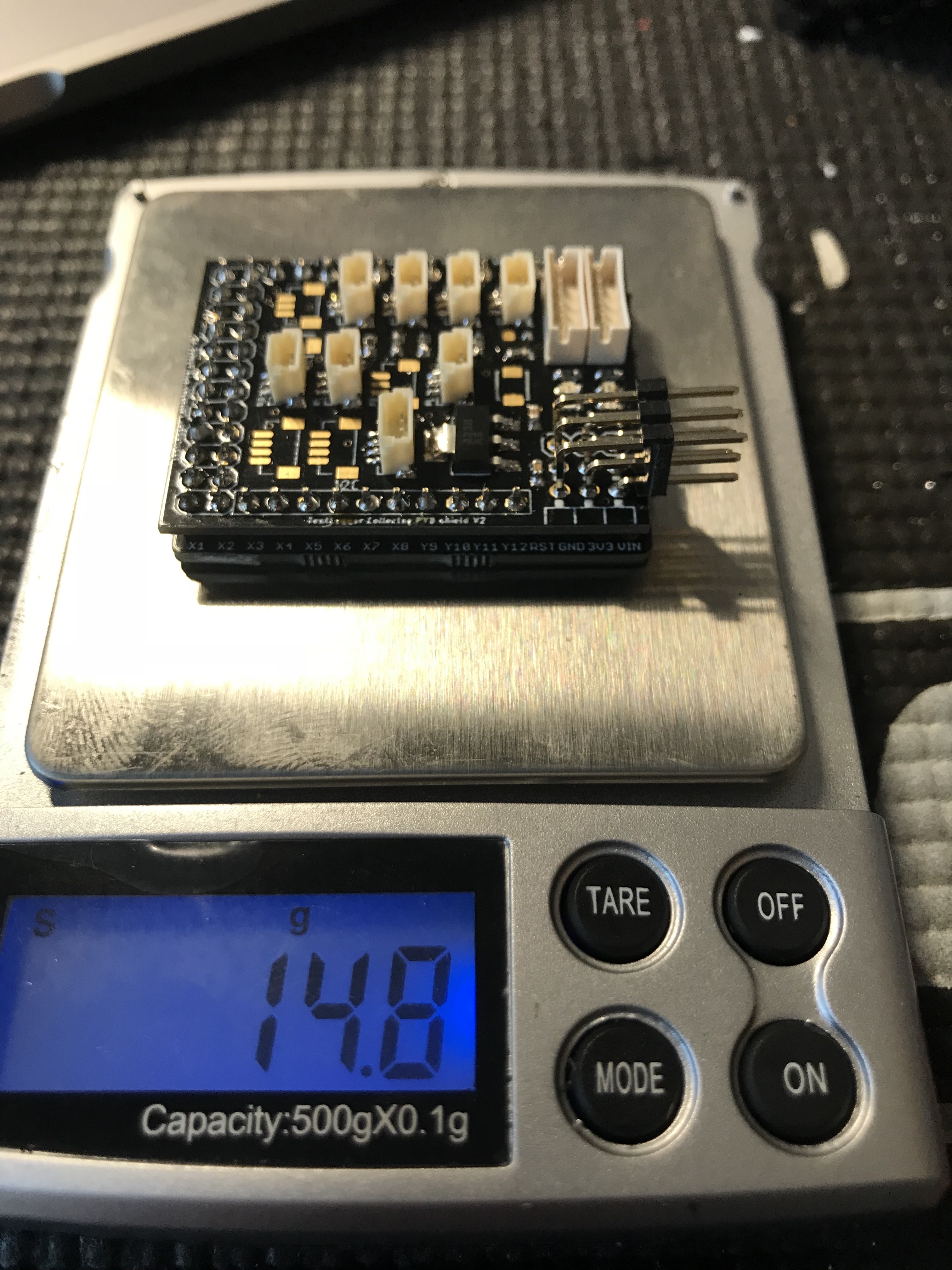
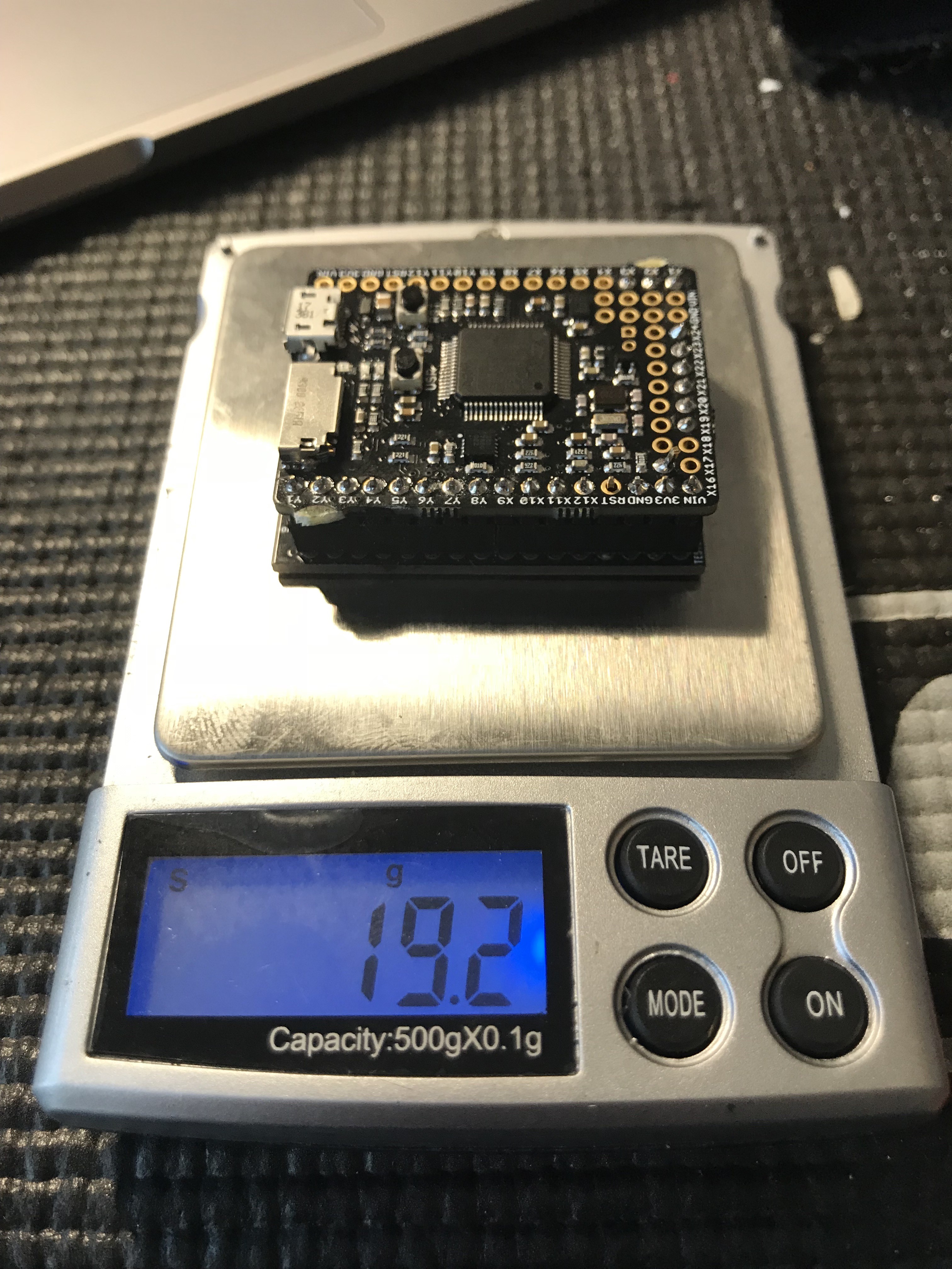
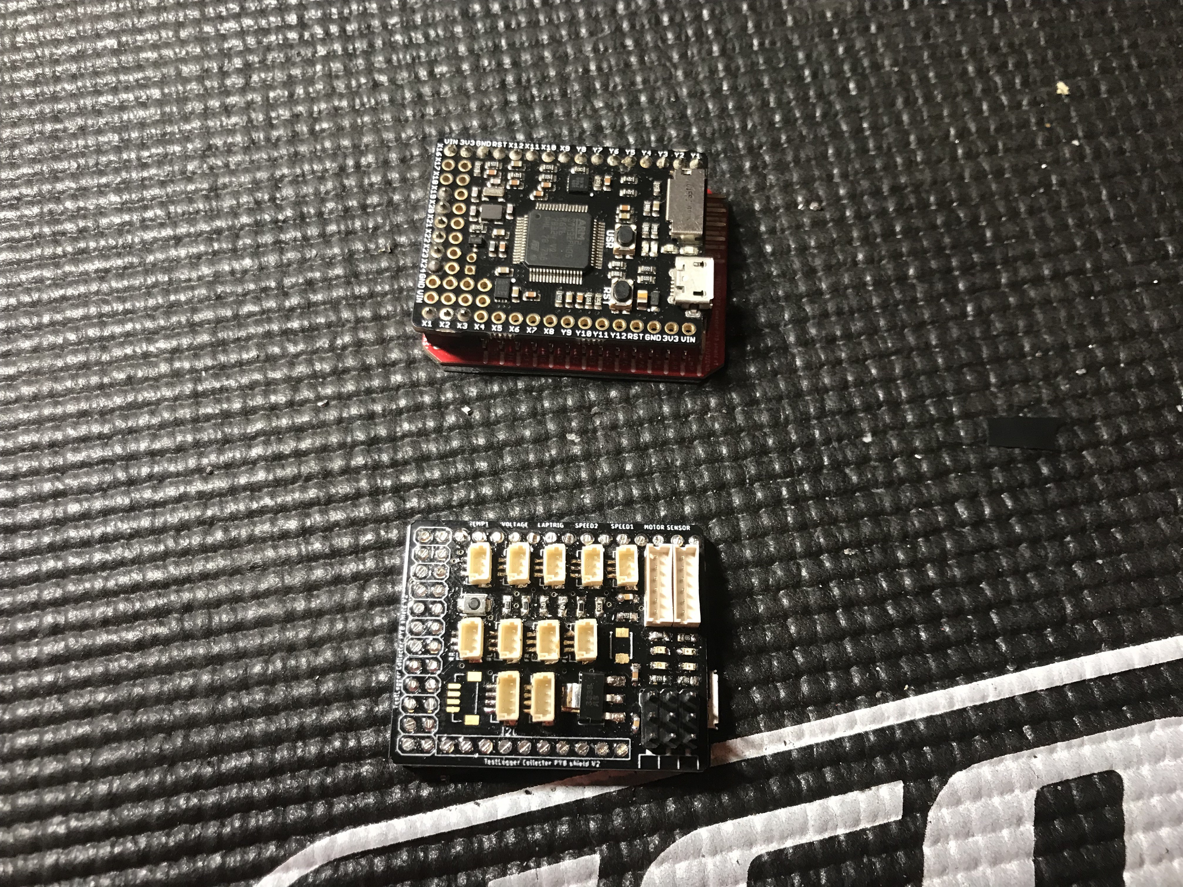
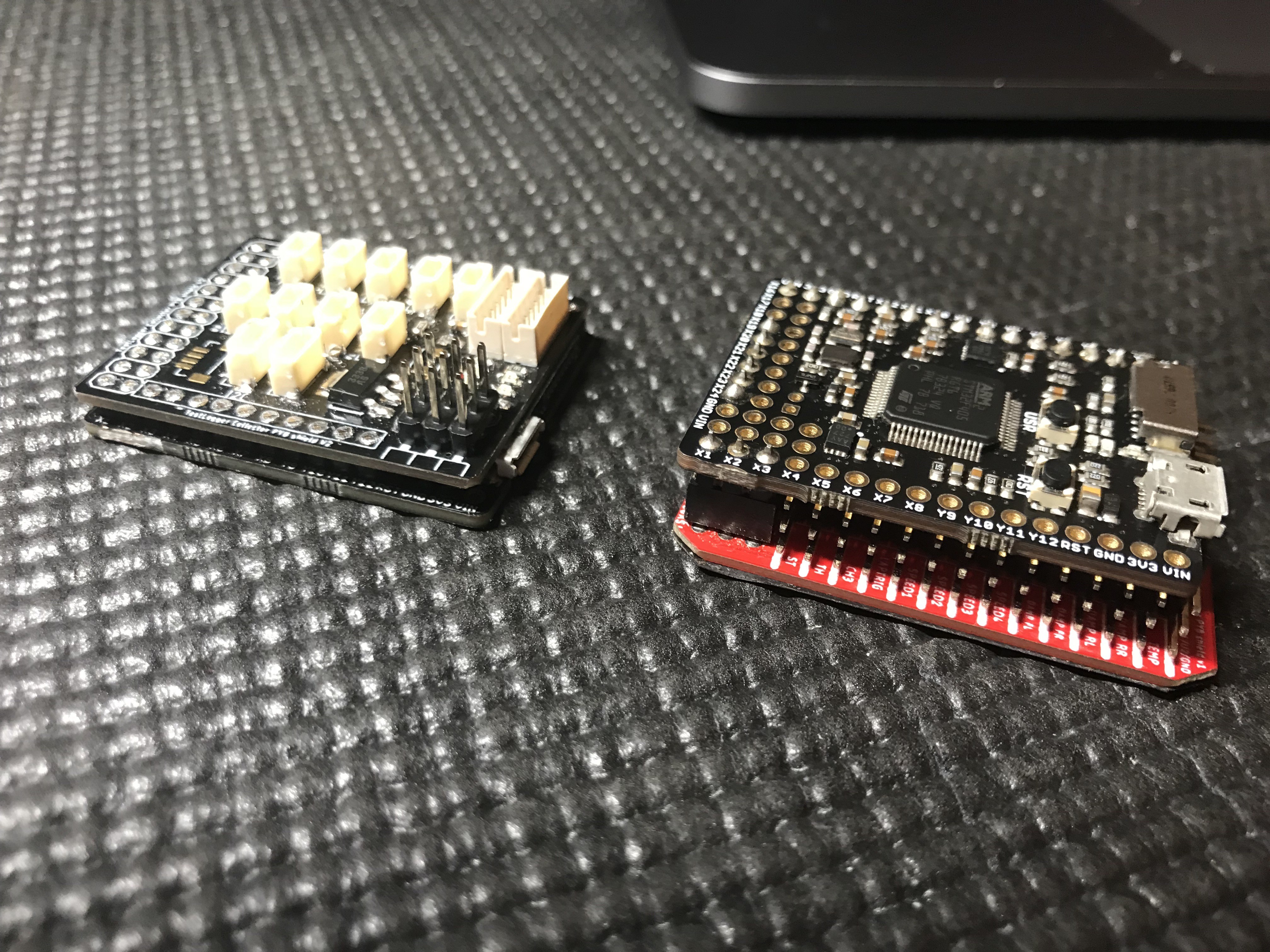
Build went pretty smooth even it was one my first times soldering SMT components. My loyal Weller WTCP 51 with 0.4mm tip did the work nicely :) As a result I got a prototype which was 4 grams lighter and few milli meters lower. Pictures shows a bit more
Testing
During the weekend I did a bit of testing with the new unit and few notes the experiences. Now the shield is soldered to PYboard and it improves the reliability on hard landings. Previous version cut the logging quite easily when it got a big hit and this was due to the board-to-boards connector headers didn't have tight enough connection. Now it didn't a got a single cut.
RPM reading from sensor port works really nice, but temperature reading I didn't test and I believe that will need some calibration.
Wiring layout was nicer to do although crimping JST-SH connectors is pain in the ass job, but I got it working. JST-SH connectors are much nicer to use as you can't connect the sensor wrong way around. Performance wise there wasn't any difference, but that wasn't expected.
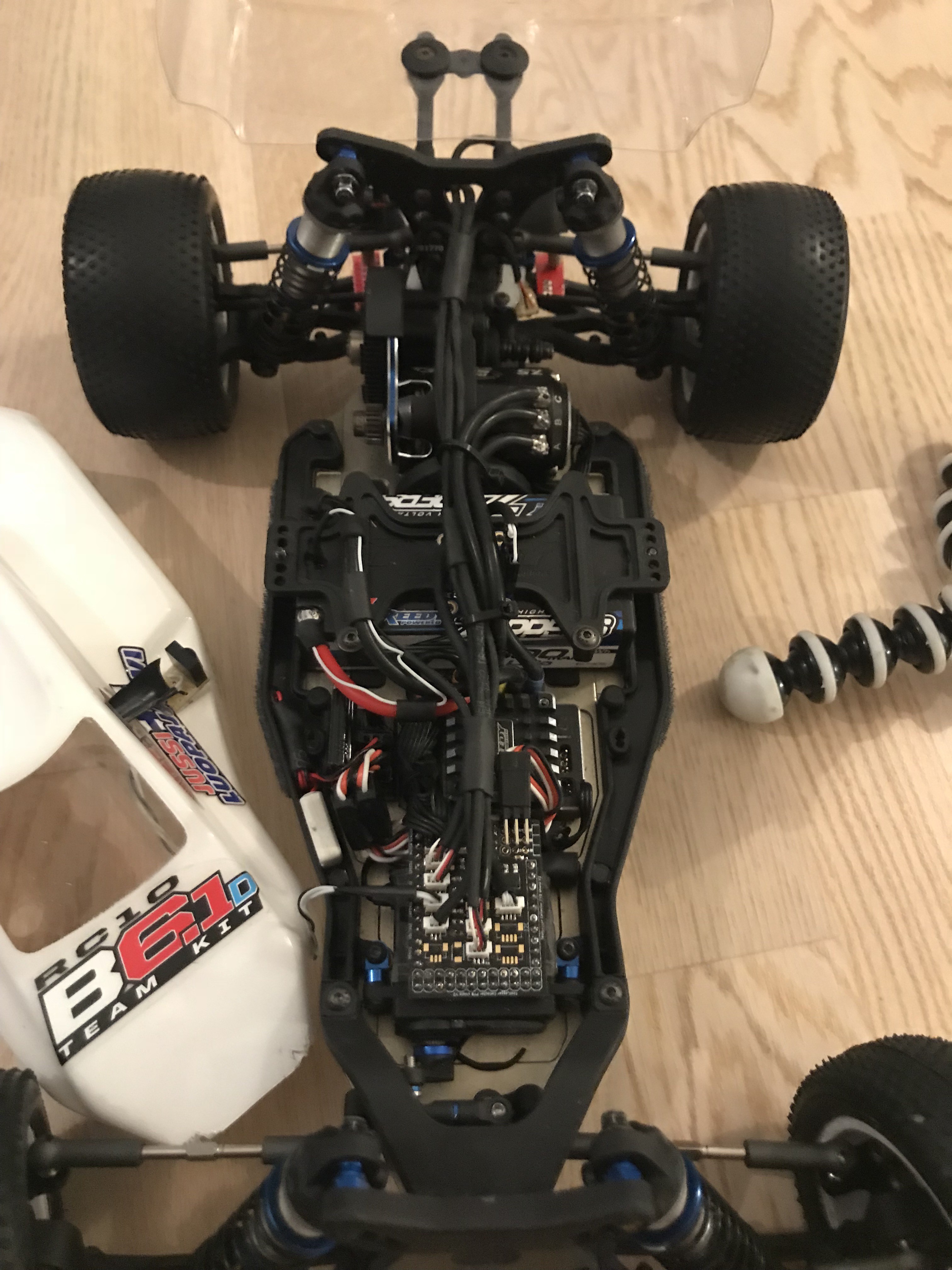
Layout
Here is a picture of my 2WD buggy with current layout. It's not super nice and tidy, but you work with it. Currently it has the measurements as follows:
- Steering position
- Throttle position
- Voltage measurement for both battery cells
- Speed from RL and RR outdrive plus the motor sensor
- RL and RR damper movement
- Laptrigger for laptimes
- G-forces for all three axis
- Yaw, Roll, Pitch
The stupidity announcement
For some reason I thought that why I need to have 5V regulator in my design as the PYboard has 3V3 regulator to have a proper voltage level for the MCU. Therefore I decided to leave the regulator out.
I just forgot a small thing that my hall sensor input needs to be at least 3V5 so 3V3 is not enough and MCU inputs are 5V tolerant. The RC car receiver provides the power for the unit and that has 6V level. This meant that hall sensor supply was 6V which isn't a problem but also the output is 6V and that's over the MCU input spec. That meant that I fried to MCUs...
Now I have the regulator in place and I have learned my lesson (hopefully). One thing I started to think about forgeting the regulator and instead using a logic level shifting for the sensor inputs. If you guys have any thoughts on topics, please share. As stated before, my experience is close to zero when it comes to electronics. Maybe I will come back to this topic later on.
New Ideas
- Combine connectors. For example combine RL and RR rear damper pots from two three pin connectors to one four pin connector. This would save space on the board and also less wires.
- Modify the damper pot sensor to remove the spring and connect directly to wishbone.
Discussions
Become a Hackaday.io Member
Create an account to leave a comment. Already have an account? Log In.
Level shifting is always possible but I completely switched to 3V3 components and regulators for all my projects now and never looked back. There should be 3V3 compatible hall effect sensors as well! Almost all new sensors work down to 2.something V or sometimes even down to 1.8V.
Are you sure? yes | no
That's a valid point and good idea to move to 3V3 components and forget the 5V level. I already investigated and there is huge amount of hall effect sensors available where minimum operating voltage is below 3V3. I was planning to order these ones for testing https://www.digikey.fi/product-detail/en/A1120LUA-T/620-1330-ND/2075330/?itemSeq=274050117 as the spec is pretty similar to the ones I use currently.
Thanks for the comment!
Are you sure? yes | no
You're welcome. It really is nice to have only 2 or 3 regulator styles (casings) in stock which you choose regarding to space and power needs...
Your project reminds me of my RC car I had as a kid, it way a Tamiya Fighter Buggy: http://www.rcscrapyard.net/tamiya-fighter-buggy.htm#1
Ooooooh those hours tuning it and waiting for those damn NiCd cells to reload. Good memories!
Are you sure? yes | no