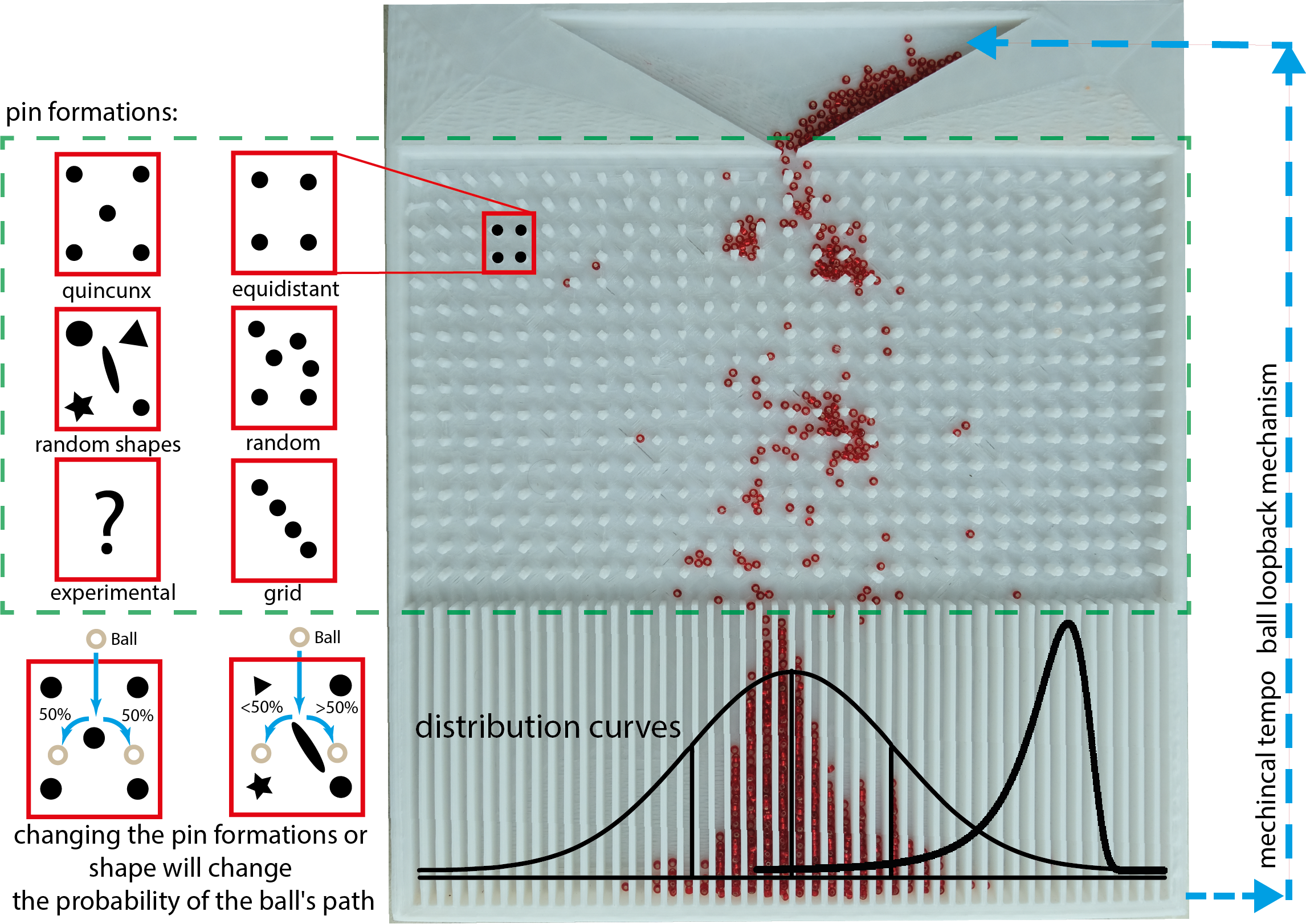
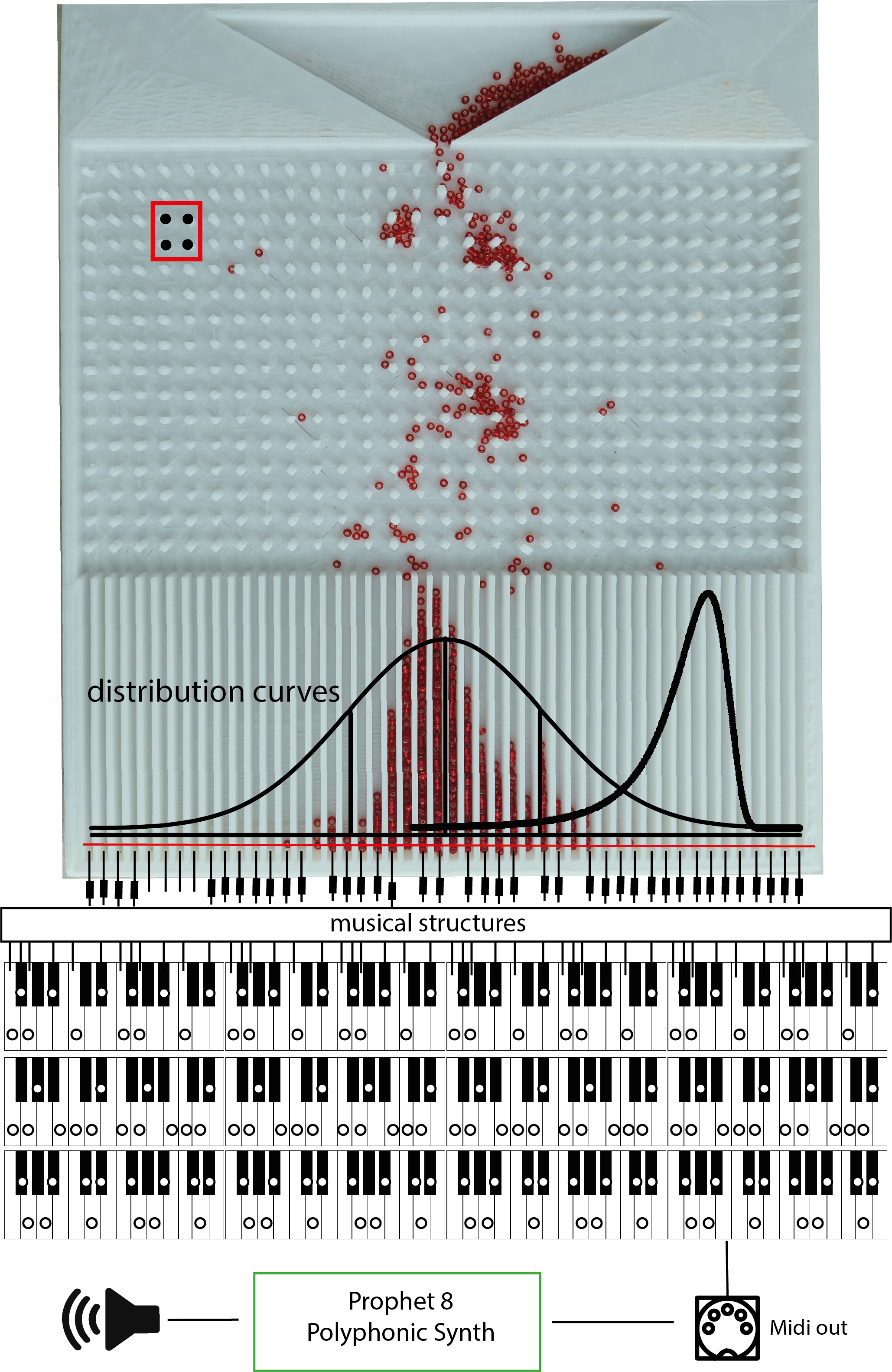
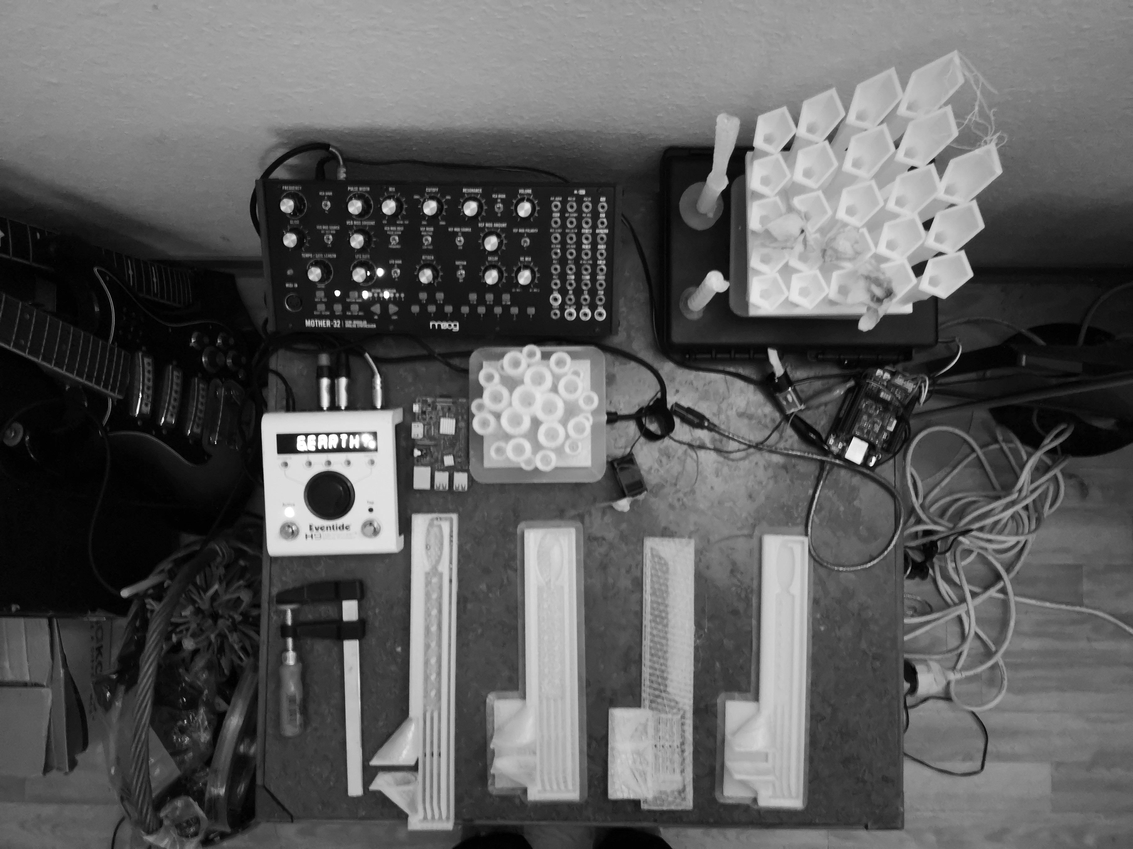
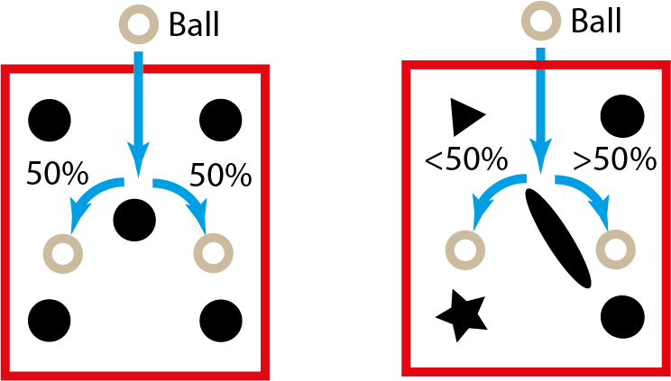
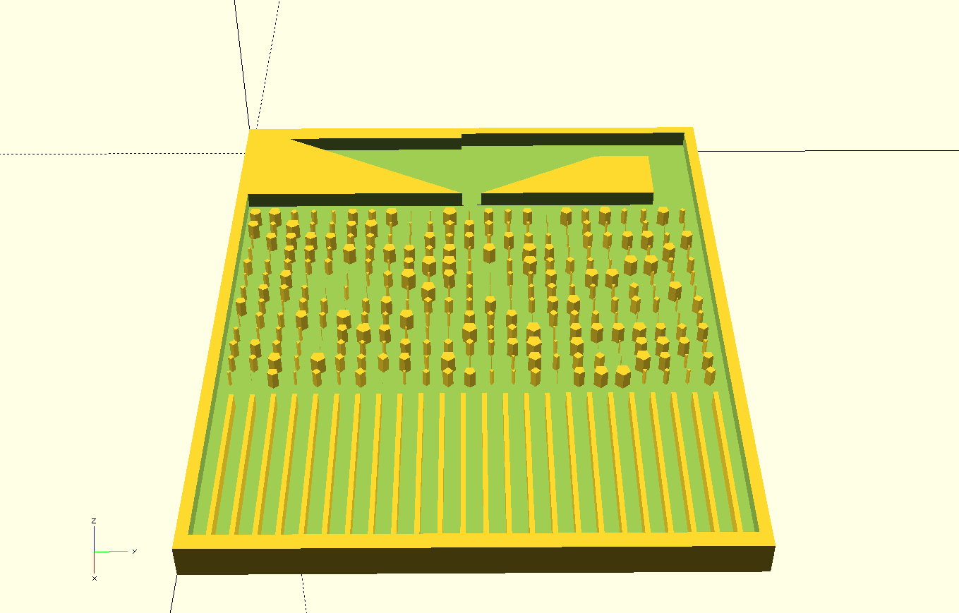
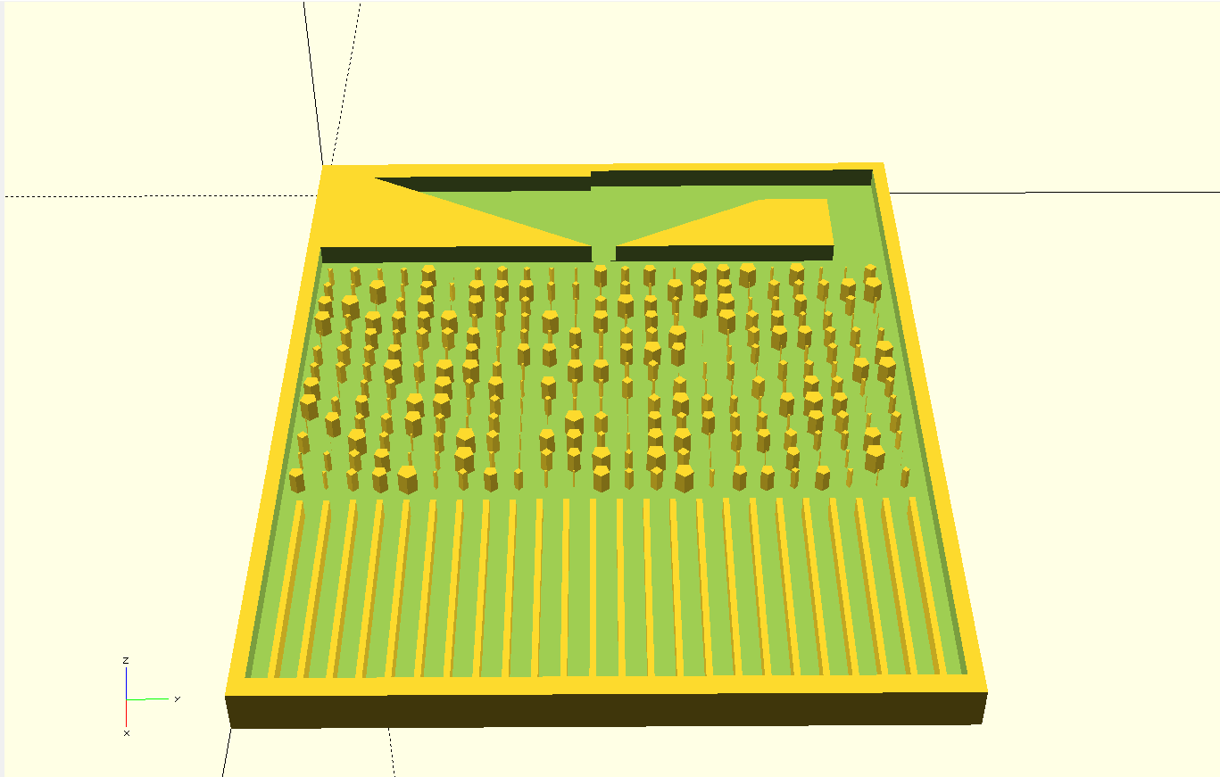
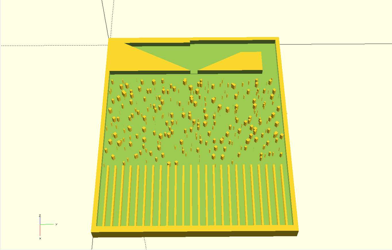
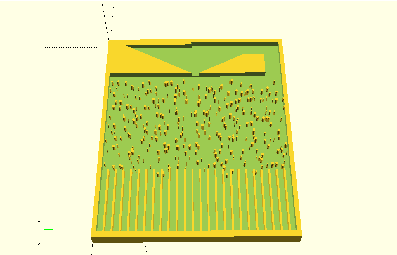
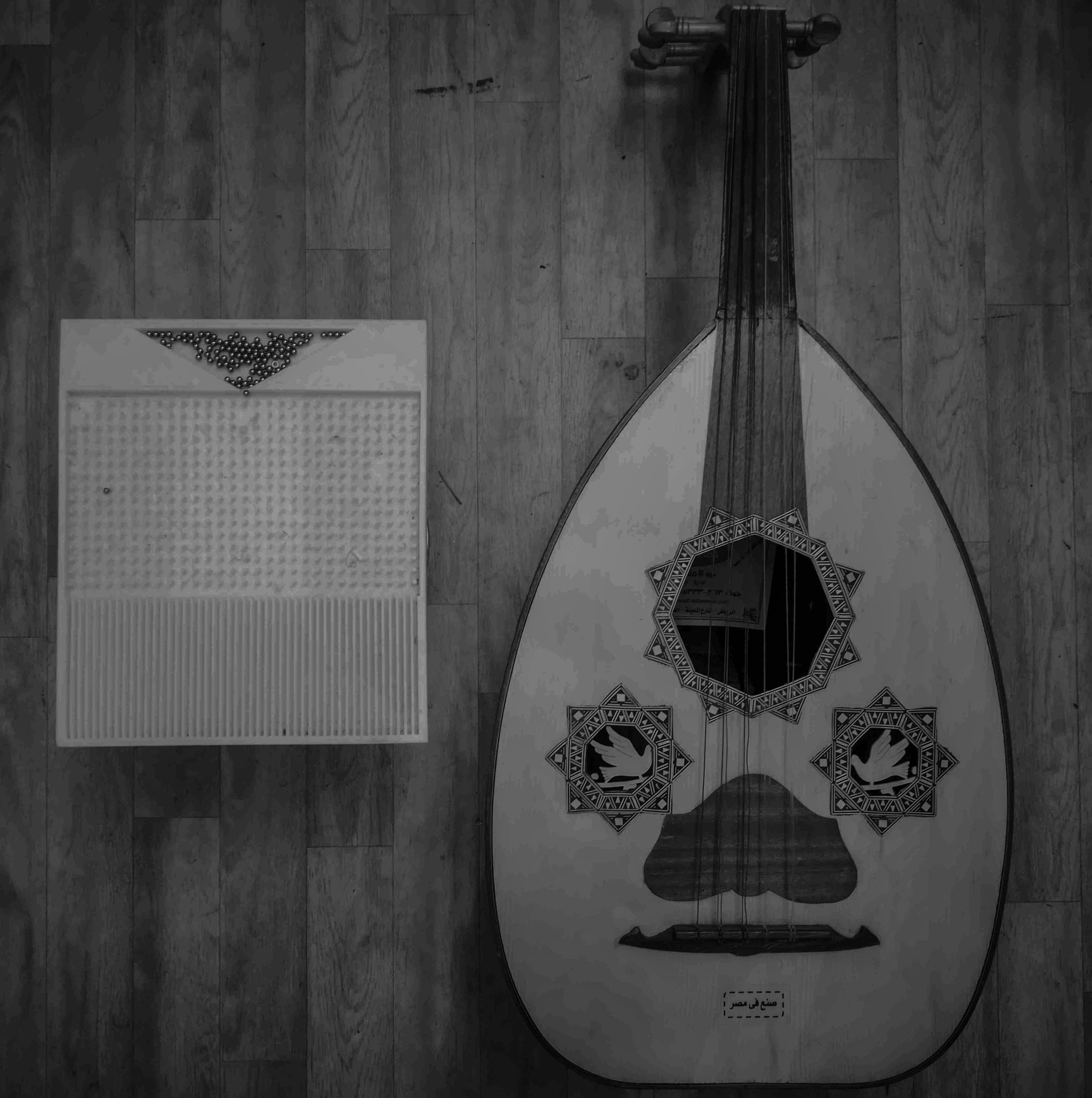
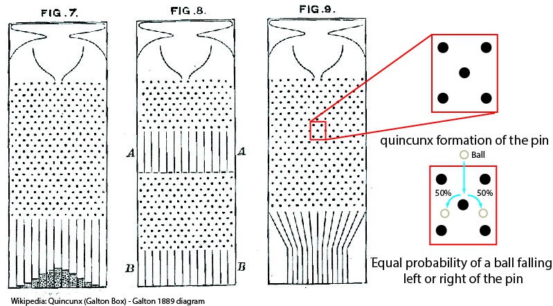
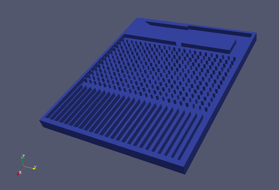
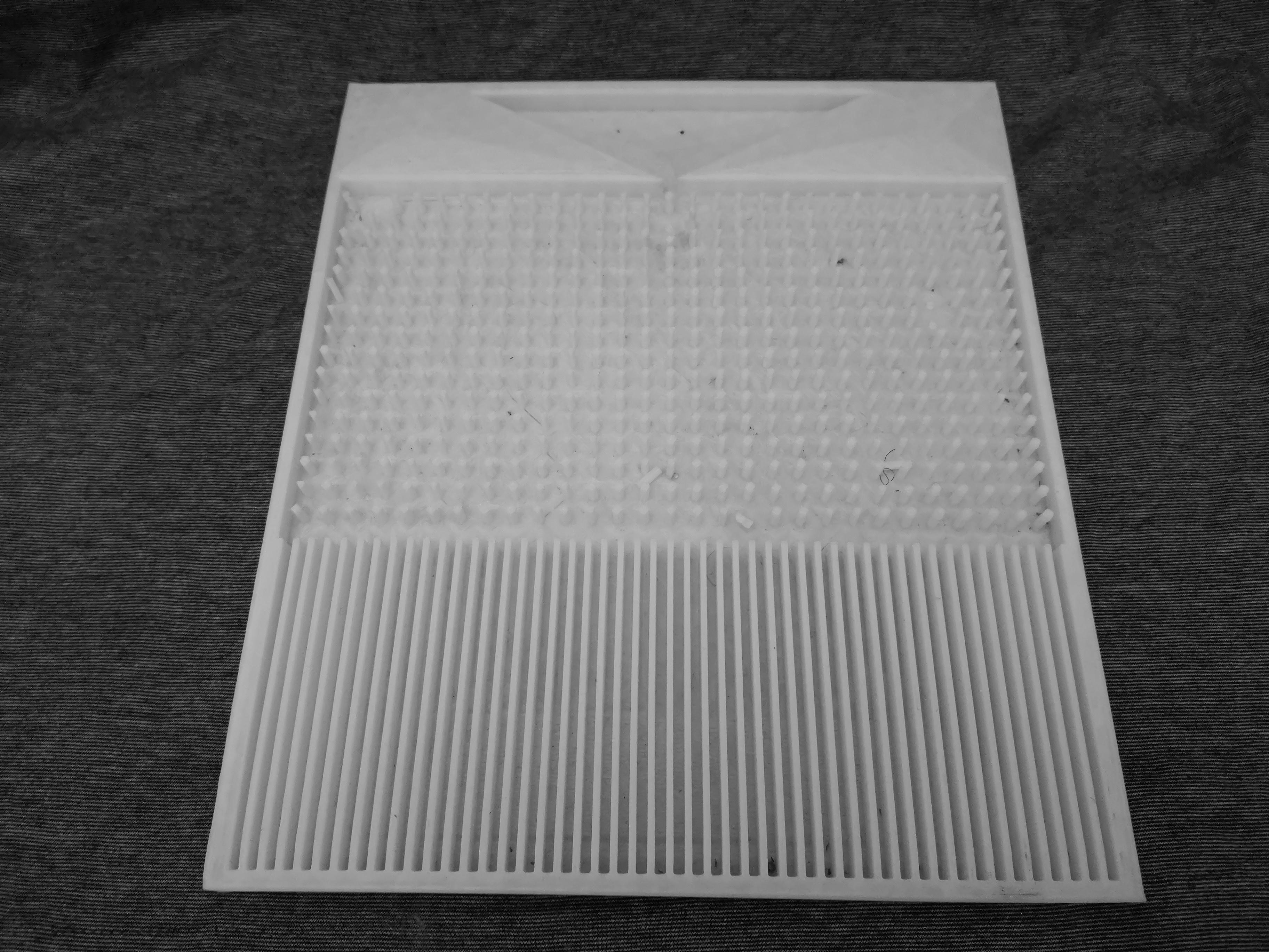
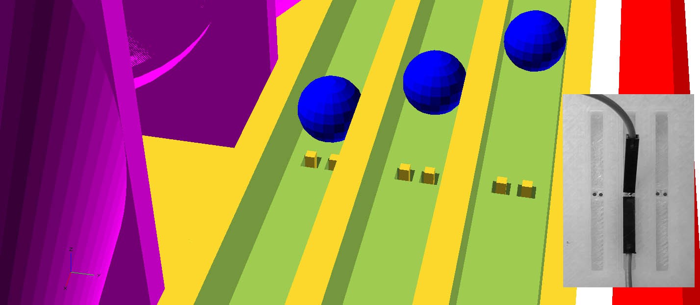
The well-tempered chaos tool-kit is a mechanical chaos based musical system that seeks to create an intuitive musical relation to the underlying generic structures of chaos in systems. Chaos is generated by the paths of ball bearings that fall through a modular geometrical structure of pins. Depending on the path of a ball the sequencer triggers sound events, such as CV, MIDI or OSC.
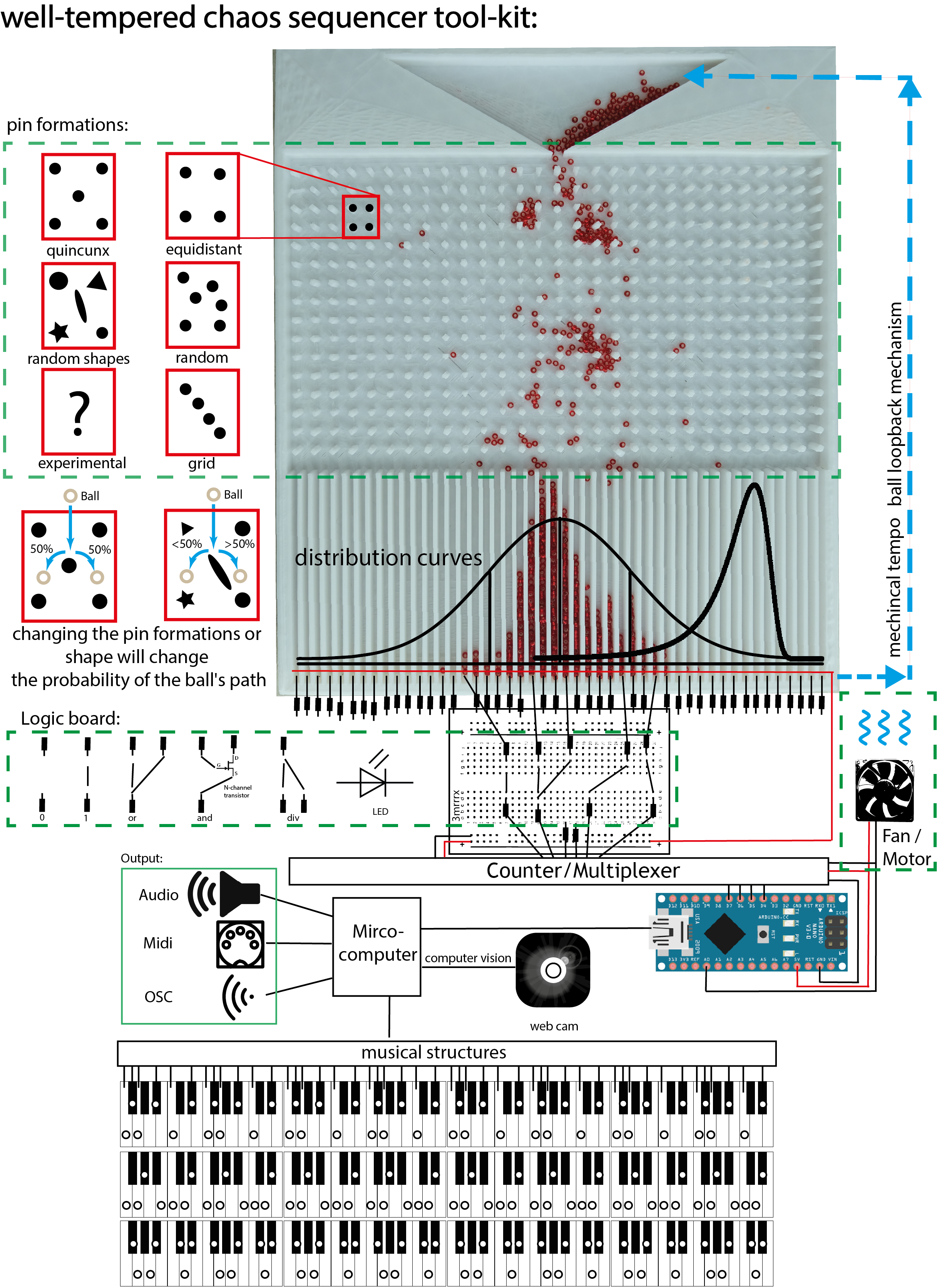
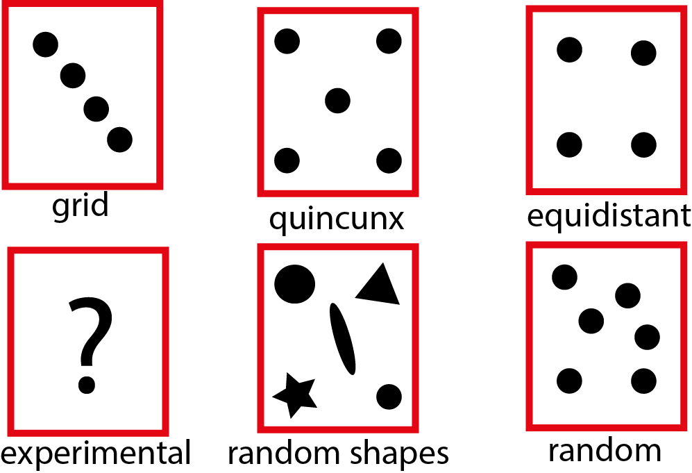
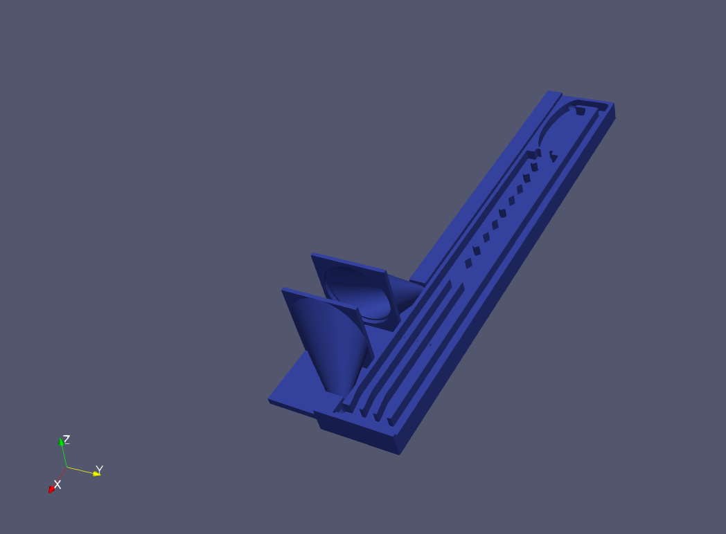
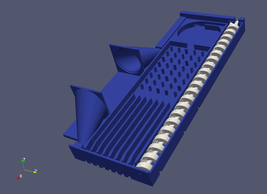
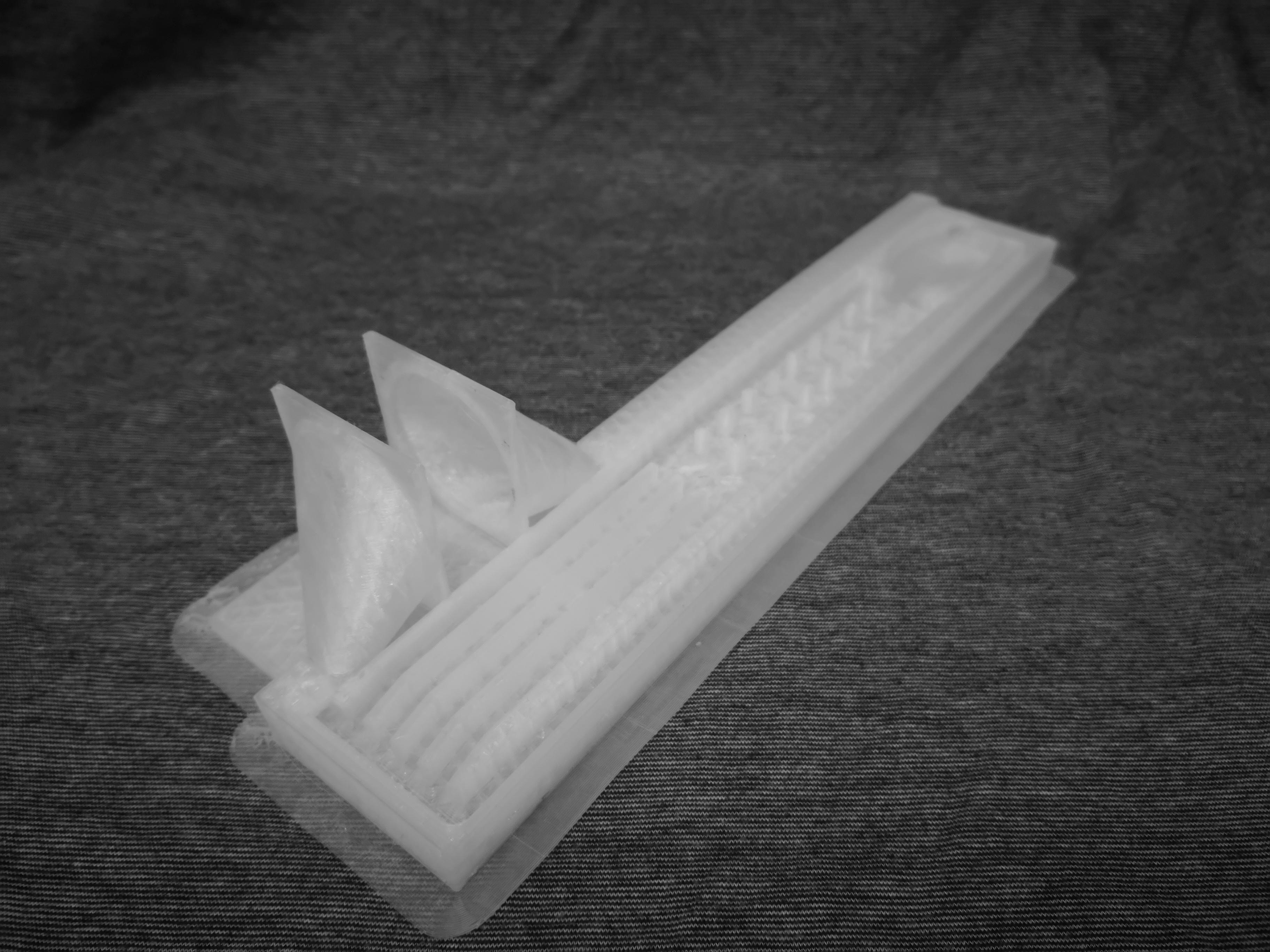
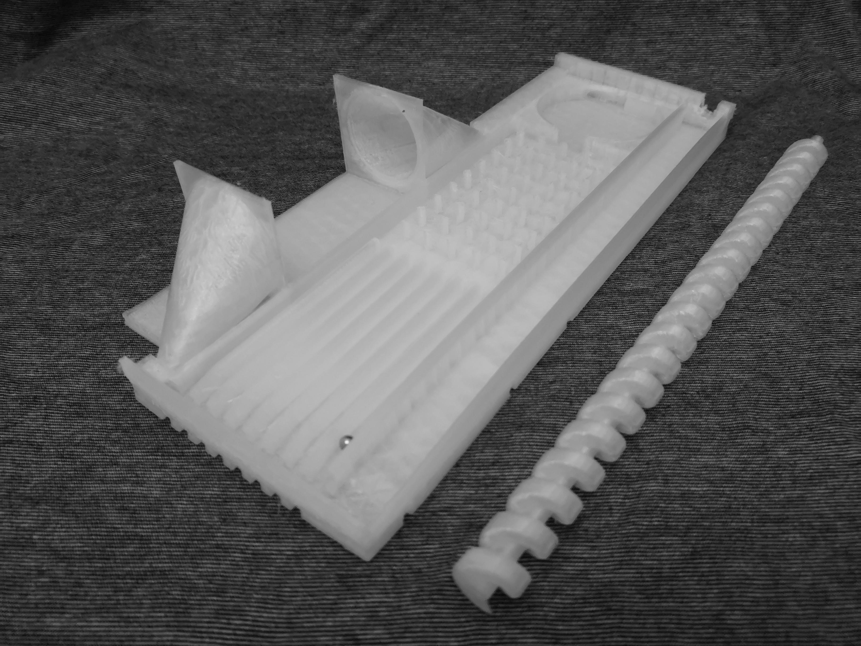
By adding a mechanism to endlessly loop the balls over the pins the chaos can be continuously sampled. Through the repeated sampling of the chaos generated by a pin formation a structure can be recognized. In return the sequencer uses this structure to trigger sound events. By changing the geometrical patterns of the pins different sound event structures can be constructed that resemble or approximate musical patterns.
When the ball loops infinitely the sequencer can become a musical object, that autonomously expresses musical structures. The idea that simulates randomness can converge through mechanical computation to different statistical distributions structures (Gaussian, non-Gaussian, Boltzmann etc.), is used to express well-tempered chaotic musical events.
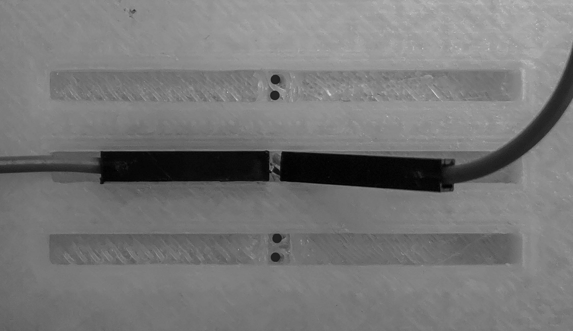
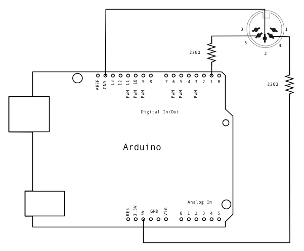
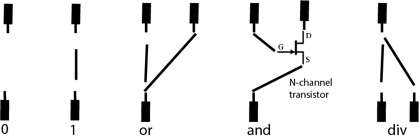
The logic of the sequencer can be extended modularly by using the bread board to create logical elements. The modularity of the system is achieved by an electric design using only non-soldered electrical components. The bearing balls counter mechanism can be built using only 2.54mm jumper cables and the board itself. This design is important to make the reproducible of the sequencer very simple.
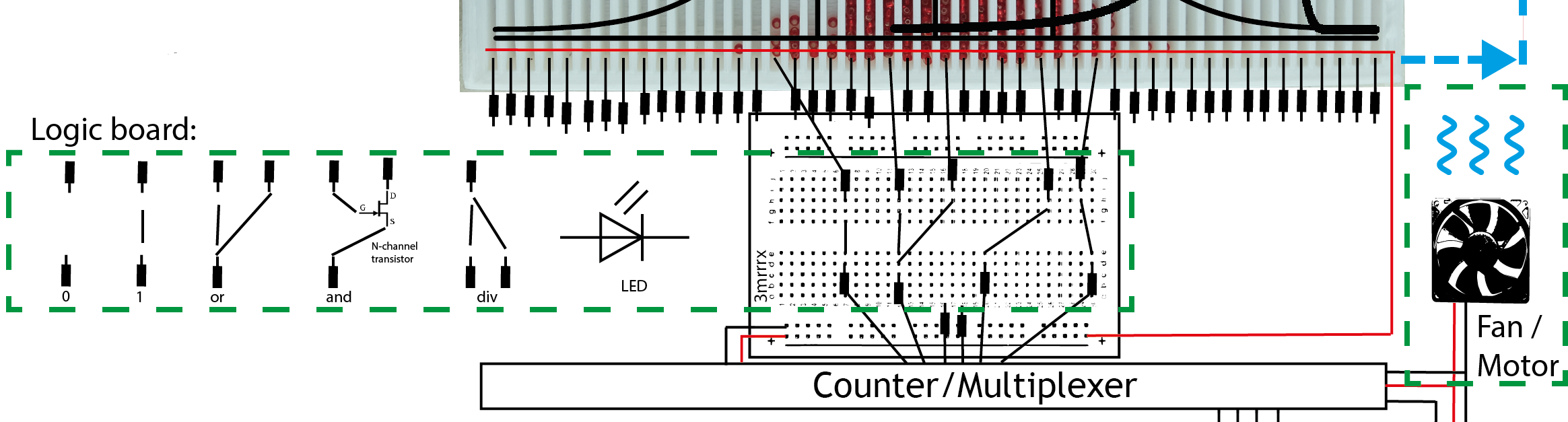
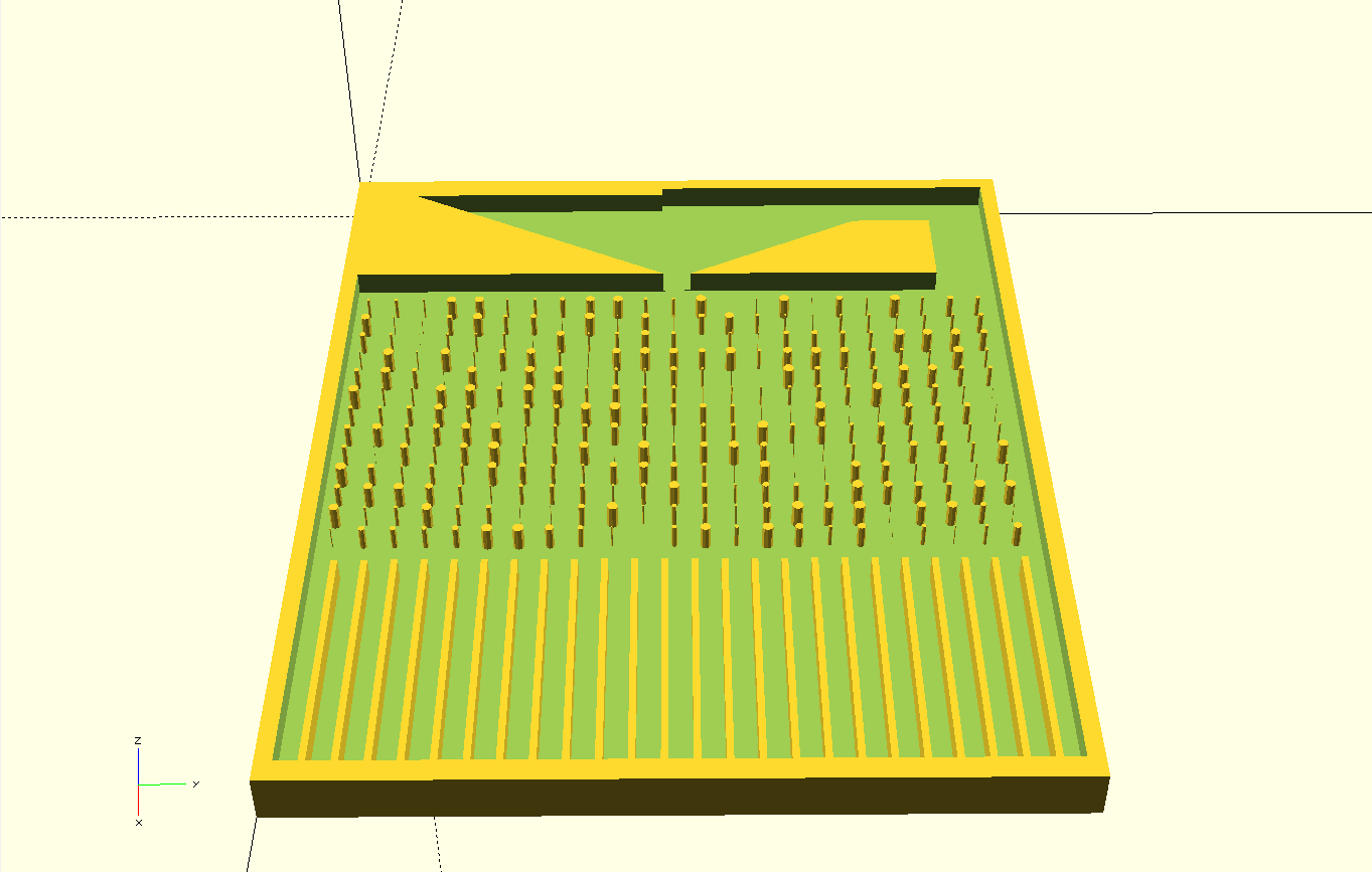
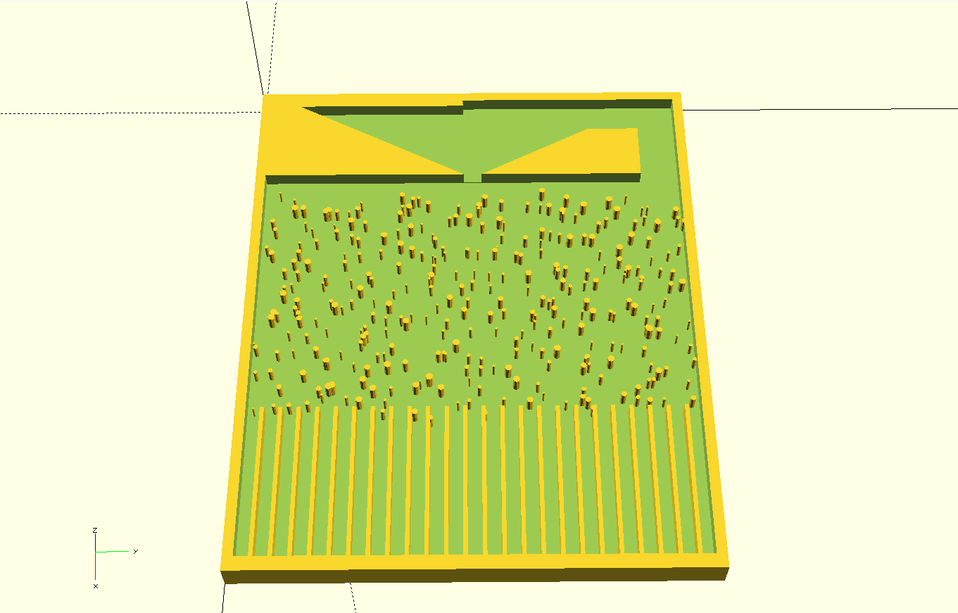
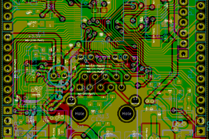
The model for the board itself is generated by a parametric script using an parametric OpenSCAD script. It takes into account the radius of the ball bearings, the dimension of the used fan or looping mechanism, as well as the maximum dimension of the whole board. The code will then automatically generate a printable STL- file, which also include holds for Jumper cables embedded. The embedded cables can then be utilized as both button switches or electrical logic boards.
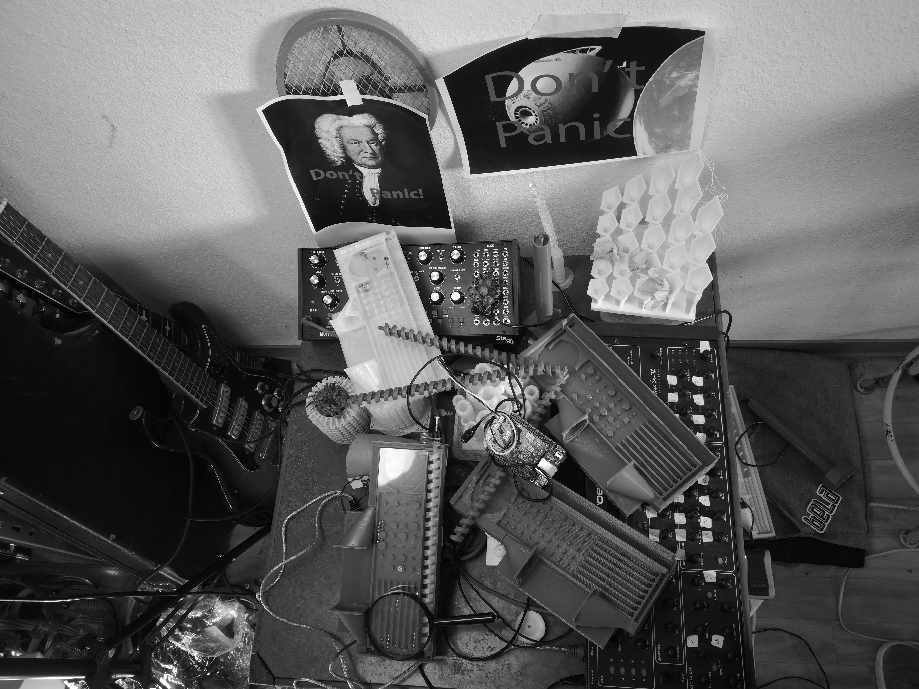
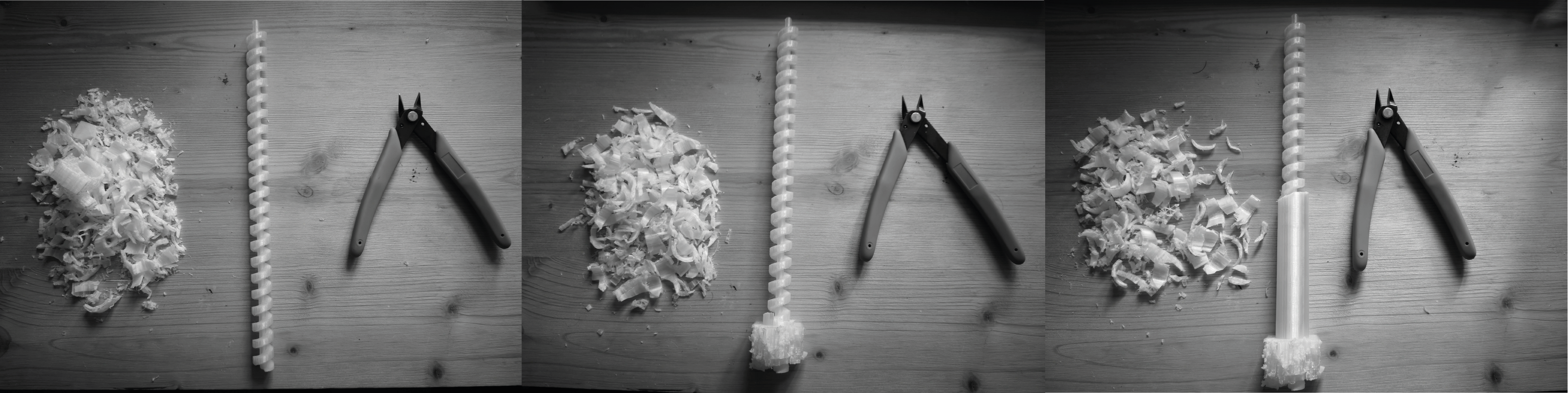
As an opensource musical instrument the whole system is designed to be easily reproducible and modular. It is designed to appeal to a very wide range of musical interests and it is constructed to make it easily accessible for a large number of people, with an open invitation to develop, share the concept and to play with the idea.
The project only uses resources that are publicly available and open source. The design and electrical schematics intended for a very basic level of technical understanding and programming. Still the design takes no compromises for modularity of both software and hardware, and opens the modularity of bread board logic to the world of music.
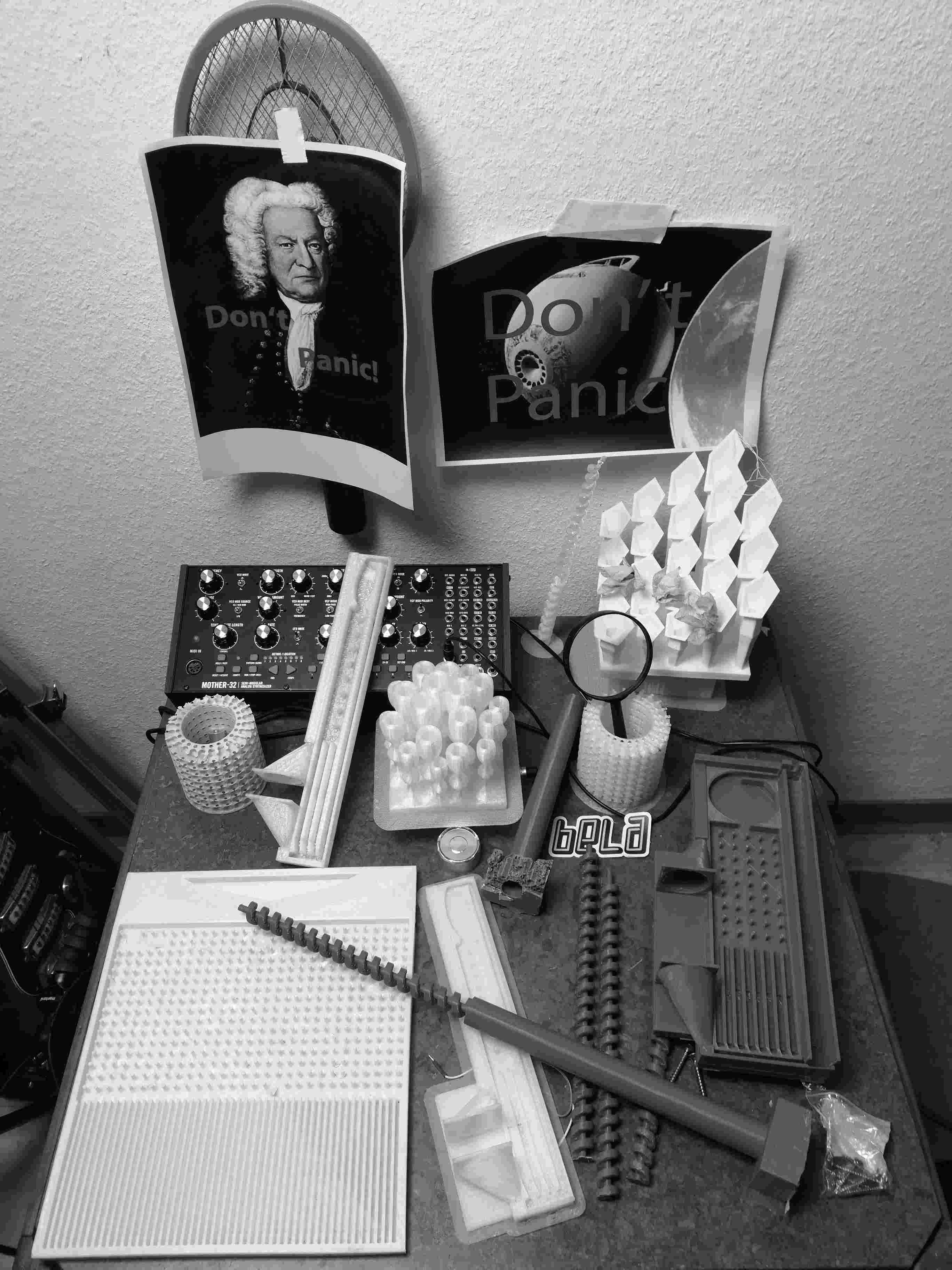
Example 1.0: Don't Panic! it's probably going to work!
Exmaple 3: Don’t Panic! This is probably improvised music!
Project logs:
2. how is the chaos sequencer tool-kit a musical instrument?
4. Don't panic! It's probably going to work!
5. Don’t Panic! This is probably a good approximation!
6. Don't Panic! This probably has MIDI!
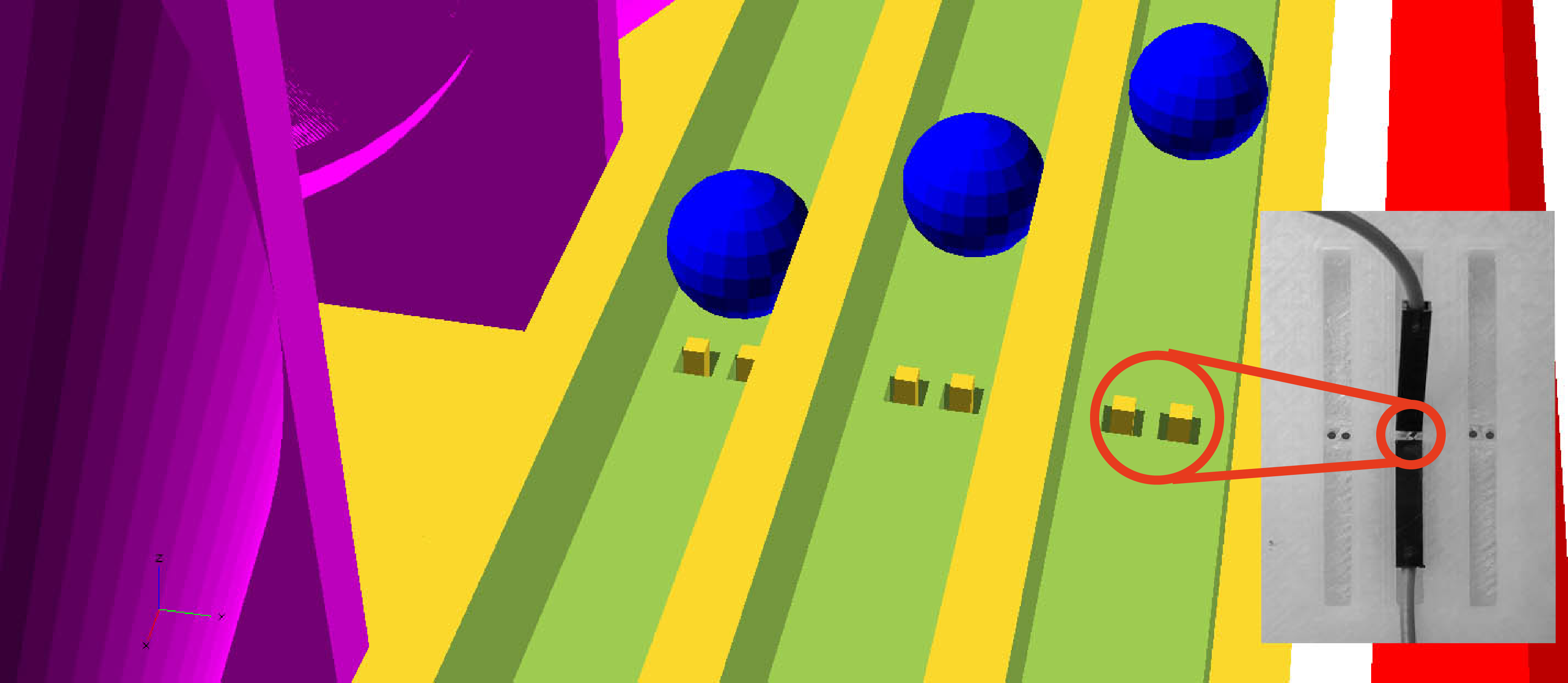
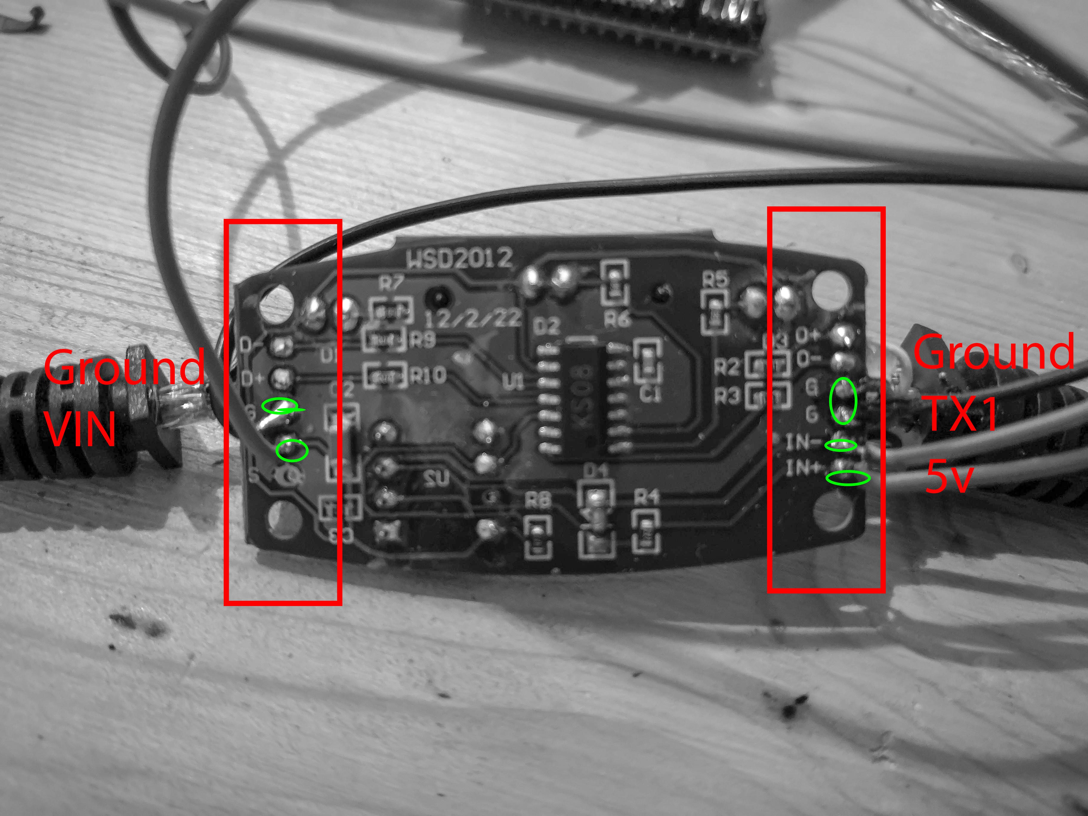
7. Don't Panic! This is probably a good sensor!
8. The boards


 Ian James
 Tom Meehan
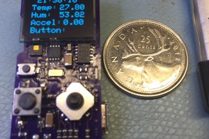
 0miker0