Close
0%
0%

LIGHT LOGIC - HIC SVNT DRACONES

Using a LED/LDR pair to form inverting Photonic logic gates.
The entire Boolean logic set handled by resistors and diodes! Who'd'a thunk

Similar projects worth following
I always read that inverted logic as in a Not, Nor or Nand can not be made with just diodes and resistors. Well, this might just break out of that box. A inverting Not gate can be made with just one led and two resistors with one of the resistors being a CdS LDR. As of July 2019 I have Buffer, Not, AND, NAND, OR, NOR. XOR and XNOR gates working. Not the fastest gates around and not going to change the world as they are currently designed but they do work and that's all I set out to prove in the first place. Who knows what the future will be for Light Logic.

All the logic elements are now coming together for the design and build of a fully functional processor that uses only diodes, resistors and a few capacitors. It will not be fast nor small in size but it will be cool as hack and be educational and fun to watch as the user will be able to visually watch and track the flow of data from one logic gate to the next. How cool is that.

The idea for this circuit came to my mind as a rough diagram back around October 5, 2018. I had been working on my #ColorChord - A Steampunk inspired creation  project and sat back thinking about the relationship between the led bar and the CdS cells. Then began thinking about the logic combinations possible and thought that perhaps a diode ( led ) / resistor ( ldr ) would provide the way to a inverting logic gate. In a flash the circuit was in my mind and a quick test set up proved it would work. The rest might be history......

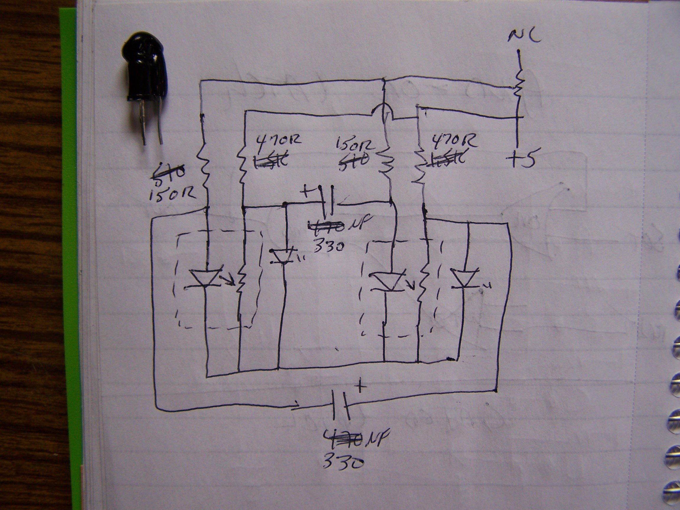
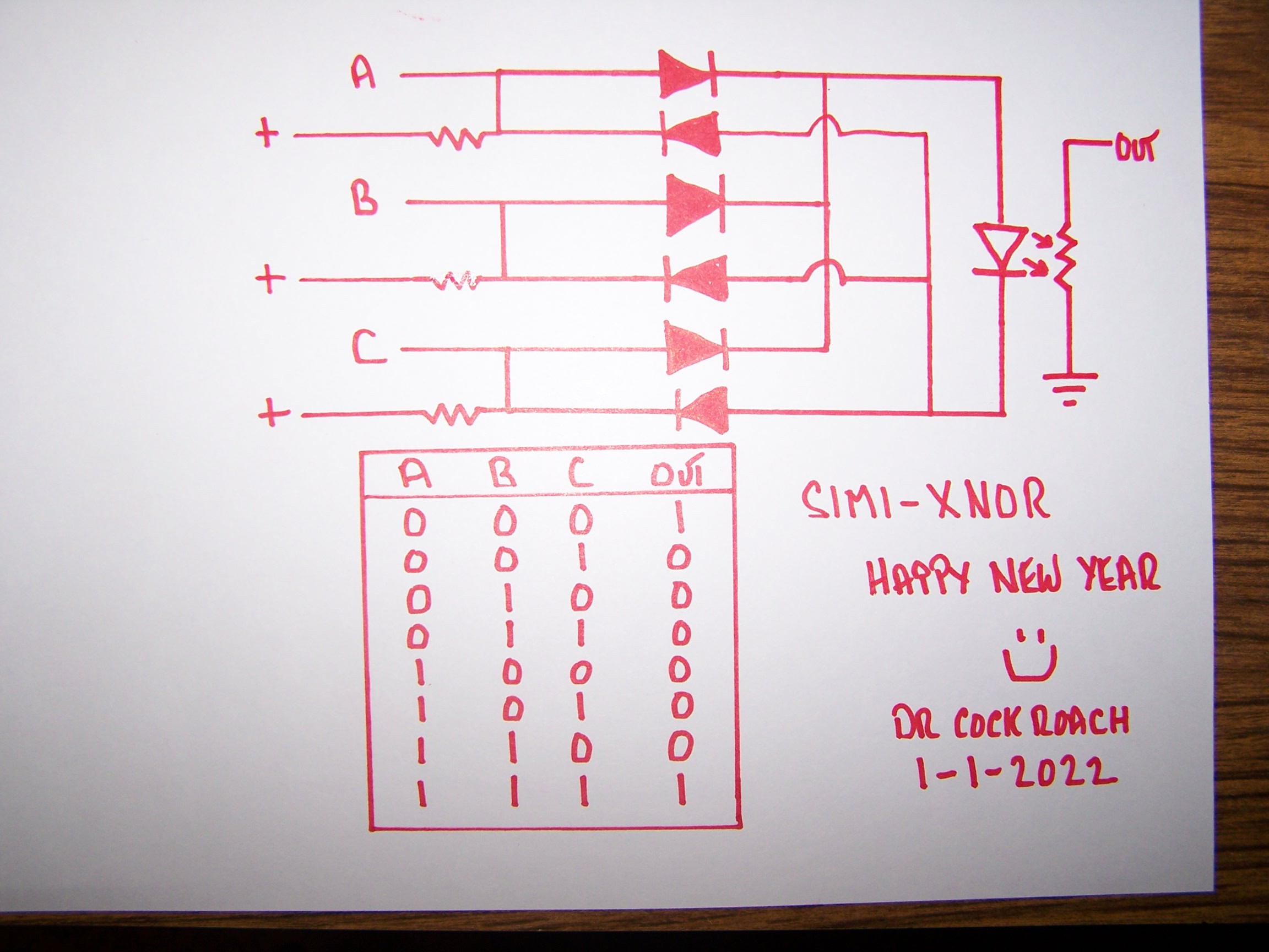
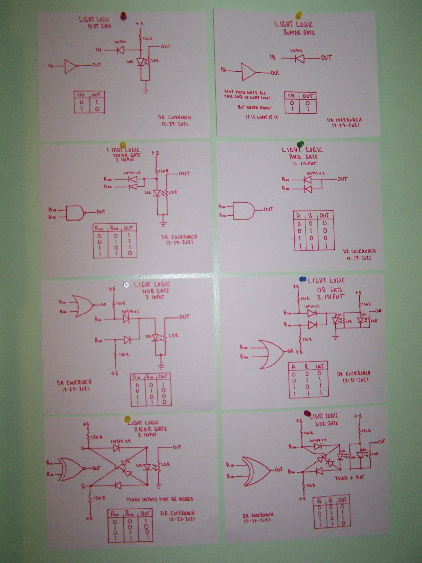
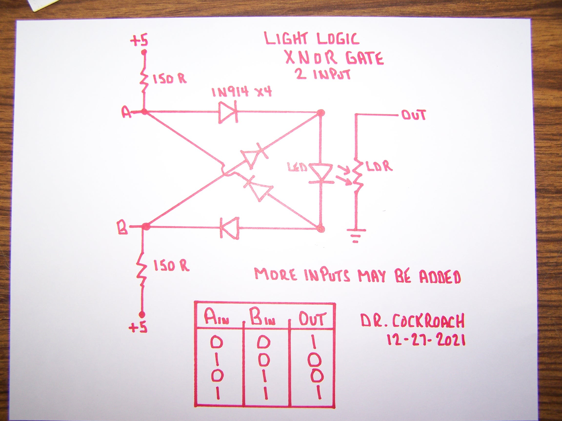
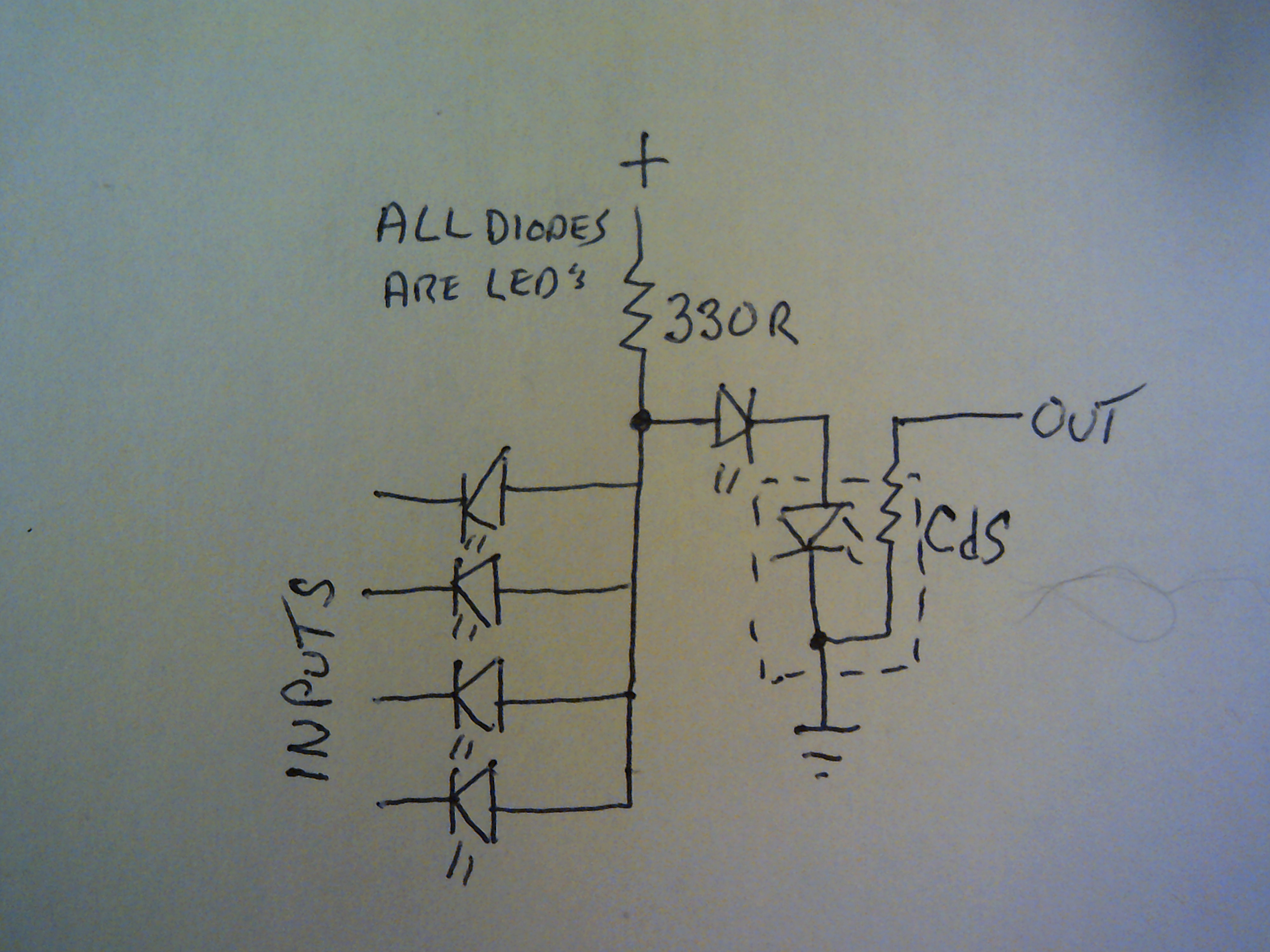
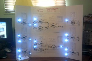
May 31, 2019 -  I now have worked out the circuits for eight individual gates. AND, NAND, Buffer, NOT, OR, NOR, XOR and XNOR. All gates use a single Light Logic element.

  • 1 × Led White
  • 1 × CdS Photo Resistor LDR
  • 1 × Switching diode 1N914 or other switching diode
  • 1 × Resistor 150 Ohms for 5 volts. Adjust value acording to voltage / current needs

  • Divide By 2 Without Transistors

    Dr. Cockroach01/11/2022 at 22:49 0 comments

    January 14, 2022 - One thing I have decided on is that when Light Logic is used in toggle latching circuits I must be more precise in matching the LDRs for their lower resistance with the Leds I am using. Normal combination logic is not generally a problem but with a clocked toggle arrangement any major mismatch leads to problems in latching or holding a latch and I have to be real careful when adjusting the voltage for everything to work the way I want. Ahhh the trials and tribulations of Light Logic.

    January 11, 2022 - Making a divide by 2 circuit with Light Logic and a astable oscillator also using vactrols has been quite the challenge. Far from being stable, it is a start and at least proves to me that Light Logic can do it all as long as I do not lose my mind in the process. The main logic is a Nand D Flip Flop along with a few other support gates.

  • Astable Rise And Fall Getting Sharper

    Dr. Cockroach01/08/2022 at 11:09 0 comments

    Just messing and now have the rise and fall times getting much sharper. I made a slight mod to the left side of the circuit where I added a second LDR to the Led to act as the output so not loading the circuit. Caps are 470uf.

  • Fine Tuning the LL Astable

    Dr. Cockroach01/05/2022 at 18:31 2 comments

    January 5, 2022 - Drifted back to fine tuning the Astable Multi-vibrator as a future clock to trigger a flip-flop counter. I could go with a simple relay but I want to give LL a fair chance. Light Logic does not need a square wave but the sharper the rise and fall time the better. Being a pair of caps are charging and discharging and a couple of CdS LDRs are in the mix, there will always be a lead and lag time to deal with.

  • A yet to be named LL X-gate

    Dr. Cockroach01/03/2022 at 20:04 6 comments

    Well, exclusive to All and Nothing OR Everything in between ;--)

    I was messing with the XNOR circuit and this came up. Perhaps it

    could be used as a lower and upper detection for a counter... I have no idea.

  • Final Circuits for Light Logic 2021

    Dr. Cockroach12/31/2021 at 23:57 3 comments

    December 31, 2021

    Not earth shattering but here are the final circuits for Light Logic. Happy New Year to everyone.

  • A much improved XNOR gate

    Dr. Cockroach12/28/2021 at 00:43 0 comments

    December 28, 2021 - After a bit of an absence I started improving on some of my Light Logic gate circuits. I was never satisfied with how my XNOR gate turned out so I ended up having a dream last night and when I woke up this morning I got to working on what I had dreamed about. The simple change is that I now feed 5 volts to the inputs continuously through a pair of 150R resistors. If there is no input at either A or B then the input is considered HIGH. If either A or B is grounded through a previous gate then the input is LOW. The Out of the LDR can be followed by a Light Logic Inverter gate to create a XOR gate or wired to any other gate as needed. I have this circuit on a bread board and it is working as it should. Remember, with Light Logic  the output MUST be through the LDR to ground to be a counted as a solid Zero / Low. Anything else is counted as a One / High

  • A All Led NAND Gate

    Dr. Cockroach04/06/2021 at 10:39 2 comments

    April 6, 2021 - Working with a free form idea of replacing input switching diodes with Leds. This is a 4 input NAND gate that shows the logic flow from input to output. This circuit works well with my existing Light Logic gates.


    Input diodes are either to ground through a prior CdS LDR  for a zero or open for a one. Minimal stress on the input Leds as the CdS minimum resistance is at a safe level of about 300R or higher.

  • The Final Sequencer Circuit - I think

    Dr. Cockroach05/08/2020 at 22:02 0 comments

    At long last I decided it was time to draw the circuit for the seven step sequencer. The switch shown is only needed if the circuit will not self start. Note that the outputs step by five. That gave me several headaches trying to figure that out......

  • Light Logic - One Year Later

    Dr. Cockroach10/28/2019 at 14:49 0 comments

    Well, it's been a year now from when I started this Light Logic project and after a slow start it has come along nicely IMO.

    Let me just list the successes I have had so far to date ( Oct 28, 2019 )

    All the basic logic gates :

         Non Inverting Buffer, Not, And, Nand, Or, Nor, Xor and Xnor

    S-R Flip Flop

    D-Latch Flip Flop

    Astable Clock Flip Flop

    Seven Step Self Clocked Sequencer

    One Bit Full Adder

    Tri-State Buffer

    From these building blocks I should be able to design a basic processor using only diodes and resistors as the main components and a hand full of capacitors for a sequencer.

    This is so much fun......Can't wait for next year :-D

  • What's in a Name - Vactrol

    Dr. Cockroach10/28/2019 at 10:19 2 comments

    I have been working with Light Logic for over a year now and the name Light Logic fits quite well for the entire logic gate family ie. Not, And, Nand, Or etc....

    What I have recently been looking into was a name for the Led/LDR pair and a few names have popped up such as....

    NPV - Nesselhaus Photonic Valve @Starhawk 

    IPV - Isolated Photo Varistor @Starhawk 

    LLPT - Light Logic Photonic Transistor @Morning.Star 

    Thanks for the cool ideas my friends.

    But @Yann Guidon / YGDES  did some digging and came up with the Vactrol.

    This opto-isolated buffer uses a Led coupled to a LDR in a very small package and the Vactrol name has been in use for quite a few years and used mainly in audio applications.

    https://en.wikipedia.org/wiki/Resistive_opto-isolator

    https://www.ebay.co.uk/itm/Audio-Optocoupler-Opto-Isolator-LED-LDR-package-vactrols-Circuit-Bending-/301866130538

    So in the end I will follow along and use the name Vactrol for my Led/LDR pair.

View all 48 project logs

Enjoy this project?

Share

Discussions

bert.hoogenboom wrote 01/19/2023 at 10:02 point

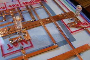
2 LED's on one LDR and you have a NOR gate. Two inverters on the input and you have  a and gate.

  Are you sure? yes | no

Dr. Cockroach wrote 01/19/2023 at 11:20 point

Oh yes, to be sure there are several ways to combine the LED's and LDR's. Currently I am recreating a 74181 4 bit ALU using my LL gates and it will be pin for pin and gate for gate exact, just much larger. If anything else, this is a great learning tool for me to think out of the box and go beyond what the older texts taught us about logic circuits and a head scratcher for others ;--)

  Are you sure? yes | no

patrick.revol wrote 12/24/2019 at 19:47 point

Hello, did you try to replace the ldr with diodes to increase the switching speed?

Pat

  Are you sure? yes | no

Dr. Cockroach wrote 12/25/2019 at 10:48 point

Hey Pat, I did a couple of trials with PIN diodes and others but did not like the results. Actually I want to go the other way and try grain of wheat bulbs paired with the LDR. Goal is to see how far back in time a electronic logic device could have been used ie. 1890's ? I am sure faster switching is possible but I am the odd sort that thinks backwards rather than forwards sometimes ;-)

  Are you sure? yes | no

Andrey V wrote 08/30/2019 at 17:47 point

Interesting project. Maybe you will implement ALU on your logic gates?

  Are you sure? yes | no

Dr. Cockroach wrote 08/30/2019 at 18:11 point

Hello Andrey, Yes I will have a full 4 bit ALU for this project. I already tested out a single bit Full Adder without any problems so I think a complete processor with my rather odd gate design will work. Not fast but will work :-)

  Are you sure? yes | no

Andrey V wrote 08/30/2019 at 18:34 point

It is very impressive! I think with years I will start to do the same things)

  Are you sure? yes | no

Dr. Cockroach wrote 08/30/2019 at 20:35 point

All I can say is that you do not need years. You have all the tools and the desire so you can do it all now. I really like your lab, very impressive :-) I just work with whatever I can obtain and if I dream it then I go and do it :-)

  Are you sure? yes | no

David H Haffner Sr wrote 04/04/2019 at 19:13 point

Hello Doc, yeah been out for awhile, I was hospitalized at the VA hospital for a time but all is better now. I wasn't sure what was going to happen so I shut down a lot of my online presense except for this place, which I consider the best fit for me anyway. Glad tto see your wonderful creation evolving into a real thing of beauty! 

  Are you sure? yes | no

Dr. Cockroach wrote 04/05/2019 at 00:28 point

Glad your OK David, I wondered where you have been. Great to have you back :-D

  Are you sure? yes | no

retrac wrote 03/29/2019 at 04:16 point

This is a creative and unusual idea.  I think both neon lamps and even incandescent bulbs would work instead of an LED.  Perhaps it's possible to build a computer faster than relay logic entirely out of neons, resistors, and photoresistors.  No semiconductors at all.

One could also use a phototransistor instead of a photoresistor.  That would be quite fast with an LED compared to a photoresistor.  Rise times in the tens of microsecond.  So many variations possible!  You've struck my curiosity, I think I'll see what I can build.  Thank you.

  Are you sure? yes | no

Dr. Cockroach wrote 03/29/2019 at 11:09 point

Hey there retrac and thanks for the input :-) Oh for sure it is doable to not use any semiconductors at all by using other light sources. But as far as speed, well, the CdS photo resistors do have a fairly long reaction time so sequential logic circuits start to have issues as soon as I ramp up the clock speed. If I use a photo transistor then I defeat the idea of this project but yes, that would be a faster way to switch :-)

A friend did send me some PIN photo diodes so going to check them out once I get this project moving again.

  Are you sure? yes | no

Samuel A. Falvo II wrote 02/19/2019 at 17:09 point

If  speed becomes a concern, which I suspect it would if you are trying to build complex logic like instruction decoders and such, then you could use a 2D mask to implement a kind of ROM-like device.  The idea is that the inputs illuminate rows, and the CdS cells detects light along the columns.  The mask, which remains interstitial between the input rows and output columns, implements the complex logic.  (Remember to keep the light from each row isolated from adjacent rows!)  This restricts your propagation delays to just three layers: the input buffering/inverting to drive the rows, and the output logic to collect the columnar results into specific outputs.  This device would be "field programmable" by just swapping out the mask with a new one.

  Are you sure? yes | no

Dr. Cockroach wrote 02/19/2019 at 18:36 point

Thank you @Samuel A. Falvo II , I had not given thought that far ahead but that sounds like a great idea to try out. Yes indeed, speed will be a major factor for more complex logic.

  Are you sure? yes | no

matseng wrote 11/08/2018 at 14:35 point

-H-o-w- (EDIT: Have) you been able to make a self-latching circuit out of this?  I.E basically just a single LDR and one LED connected in series and pointed to each other?  

At full darkness the resistance of the LDR is high enough to not light up the LED, then you temporary short the LDR to light up the LED causing the resistance of the LDR to drop enough to keep the LED on permanently.

If you then temporary short the LED so it will go dark causing the LDR to be high-resistance keeping the LED in a permanent off-state.

(Some current limiting might be a good thing here...)

I played around with it a bit, but my LEDs are so sensitive that they light up enough to cascade-trigger the LDR to full-on.

If it would be possible then a memory matrix rivaling the first core memories in density could be within reach.

  Are you sure? yes | no

Dr. Cockroach wrote 11/08/2018 at 16:04 point

Hey there, The Not, Nor and Nand gates interconnect and work just like their transistor counterparts.... The only connection between the Led and Ldr is their common ground. The led is turned on and off by the previous gate by shunting to ground. So far my s-r latch and D latch are working fine as well as the master slave J-K using the clock signal from the astable that is also using the led/ldr combo :-) Excess room/sun light needs to be shielded to some extent. The self latching idea sounds like something for me to try out....Need to look into it :-)

  Are you sure? yes | no

Dr. Cockroach wrote 11/14/2018 at 10:40 point

It is very possible :-D

  Are you sure? yes | no

matseng wrote 10/29/2018 at 09:41 point

So this means that each gate have both voltage and current gain... Or else the signal would "fizzle out" after chain of a few gates.   So possibly it could be possible to make an (very bandwidth limited) audio amplifier out of LEDs and LDR's then.

[ The department of ancient knowledge wants to remind you all that the word fizzle meant "to break wind without making noise" back 500 years ago ;-) ]

  Are you sure? yes | no

Dr. Cockroach wrote 10/29/2018 at 10:45 point

Fizzle, I can still learn something new every day ;-)

Yep, each gate refreshes the output levels so I might give the gates a try at audio and hear what happens. I do not expect Hi-Fi quality though ;-)

One issue to contend with is the latency of the CdS material as that is limiting the speed of the gates.

  Are you sure? yes | no

Yann Guidon / YGDES wrote 10/15/2018 at 21:18 point

Did you see http://www.decodesystems.com/nixie.html ?
It shows one example of ROM/decoder with CdS cells :-D

  Are you sure? yes | no

Dr. Cockroach wrote 10/15/2018 at 15:08 point

Thanks Yann for bringing me out of the darkness. Glad you caught this :-)

  Are you sure? yes | no

Yann Guidon / YGDES wrote 10/15/2018 at 18:41 point

it's a pleasure to see you hacking, and I'm glad your experiments are rewarded !

  Are you sure? yes | no

Eric Hertz wrote 10/14/2018 at 05:43 point

Breaking all the rules! Perfect teaching-aide, too! Nicely done.

  Are you sure? yes | no

Dr. Cockroach wrote 10/14/2018 at 07:31 point

Broke / Bend, I lost track :-) Thanks :-)

  Are you sure? yes | no

Yann Guidon / YGDES wrote 10/14/2018 at 03:52 point

Is there an "optimisation" to merge the input diodes with the LED function ?

Just have the CdR as "high side" resistor, and the 1N4148 are replaced by LEDs that both shine on the photocell :-)

  Are you sure? yes | no

Dr. Cockroach wrote 10/14/2018 at 07:29 point

I was planning on trying to mount real small SMD leds to the CdS and someone else mentioned using fiber optic cables to couple the gates to each other...

  Are you sure? yes | no

Starhawk wrote 10/14/2018 at 01:50 point

You can get LED night lights with CdS cells inside at Dolla Tree, IIRC...

  Are you sure? yes | no

Dr. Cockroach wrote 10/14/2018 at 07:30 point

My Dollar Tree keeps running out of them but I will keep checking my store :-)

  Are you sure? yes | no

Kelly Heaton wrote 10/11/2018 at 13:29 point

What are the specs of your CdS Photo Resistor LDR (what resistance in light and dark)?

  Are you sure? yes | no

Dr. Cockroach wrote 10/11/2018 at 14:55 point

I read about 40K blacked out and 200 Ohms very bright. These Ldrs are from night lights sold at Wal-Mart. @Morning.Star  sent me one of his that went to almost inf when blacked out and about 30 Ohms lighted but I misplaced it for the moment :-)
 For small purchases, the four pack of led night lights with the Ldr runs about $5 and besides the Ldr and Smd led there are a few more useful parts to hack out of them ;-)

  Are you sure? yes | no

Kelly Heaton wrote 10/12/2018 at 01:47 point

Thanks!

  Are you sure? yes | no

Peabody1929 wrote 10/10/2018 at 15:51 point

How about using fiber optic cable to connect the LED output to the photocell input?  A 2 input gate would have two cables over a single photocell.  The fiber optic cable could even be the "wiring" between gates.

  Are you sure? yes | no

Dr. Cockroach wrote 10/10/2018 at 16:26 point

That has been mentioned as well as attaching very small SMD leds to the face of the CdS. Many ways to try this out and looking forward to testing them all :-) Thanks :-)

  Are you sure? yes | no

Morning.Star wrote 10/09/2018 at 05:21 point

Thats what I've been told, not possible. Lol, sounds like a challenge :-D

This is impressive, low level theory and technology. Nice discovery dude. Nice work! :-)

  Are you sure? yes | no

Dr. Cockroach wrote 10/09/2018 at 11:01 point

It looks as if I am going to have to write my own book on how this works. The rules have changed a little bit ;-)

  Are you sure? yes | no

Similar Projects

Does this project spark your interest?

Become a member to follow this project and never miss any updates