 Dr. Cockroach
This test project will be a Johnson Counter with 7 segment hex display.
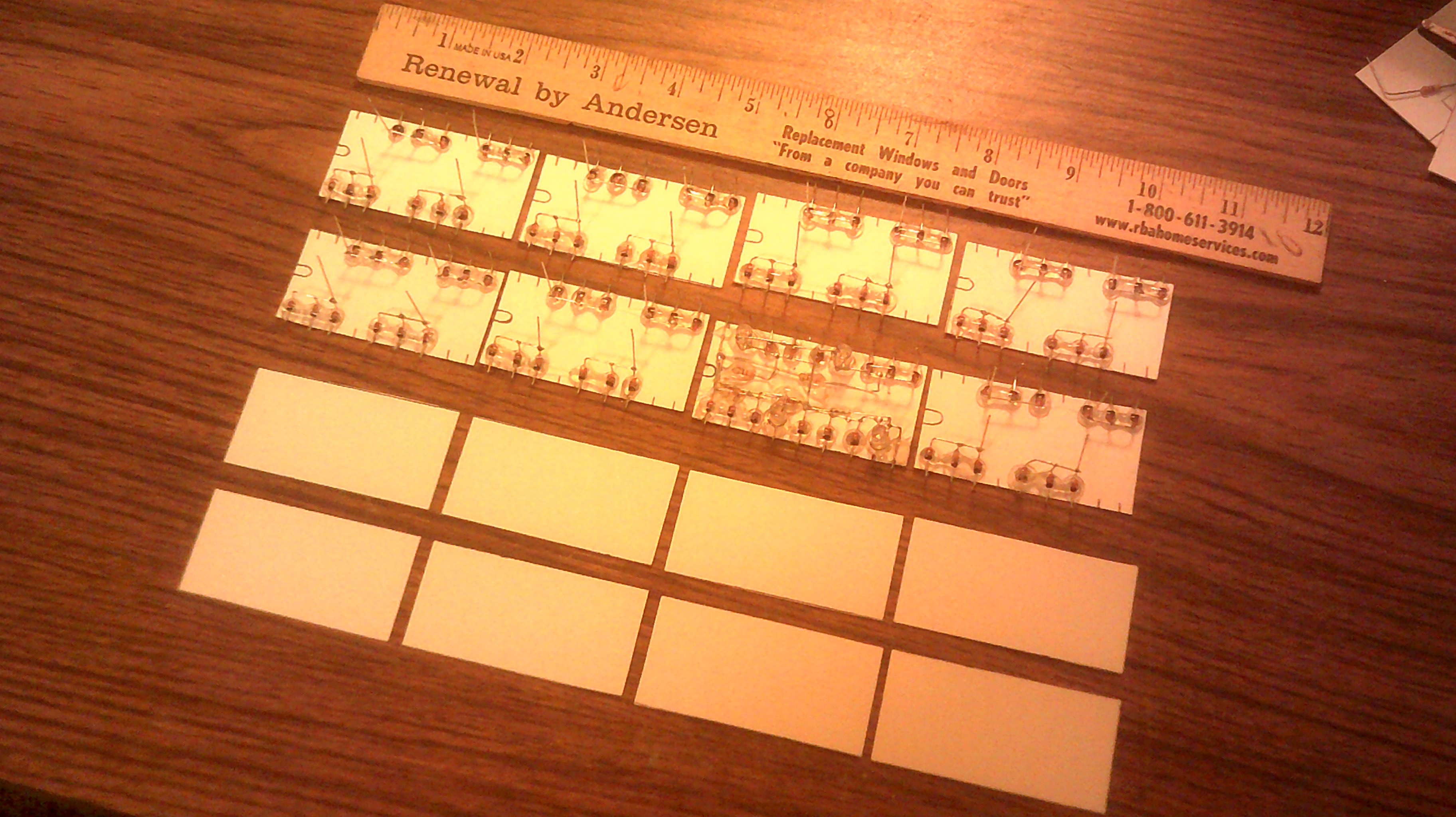
First flip-flop wired, seven more to finish.
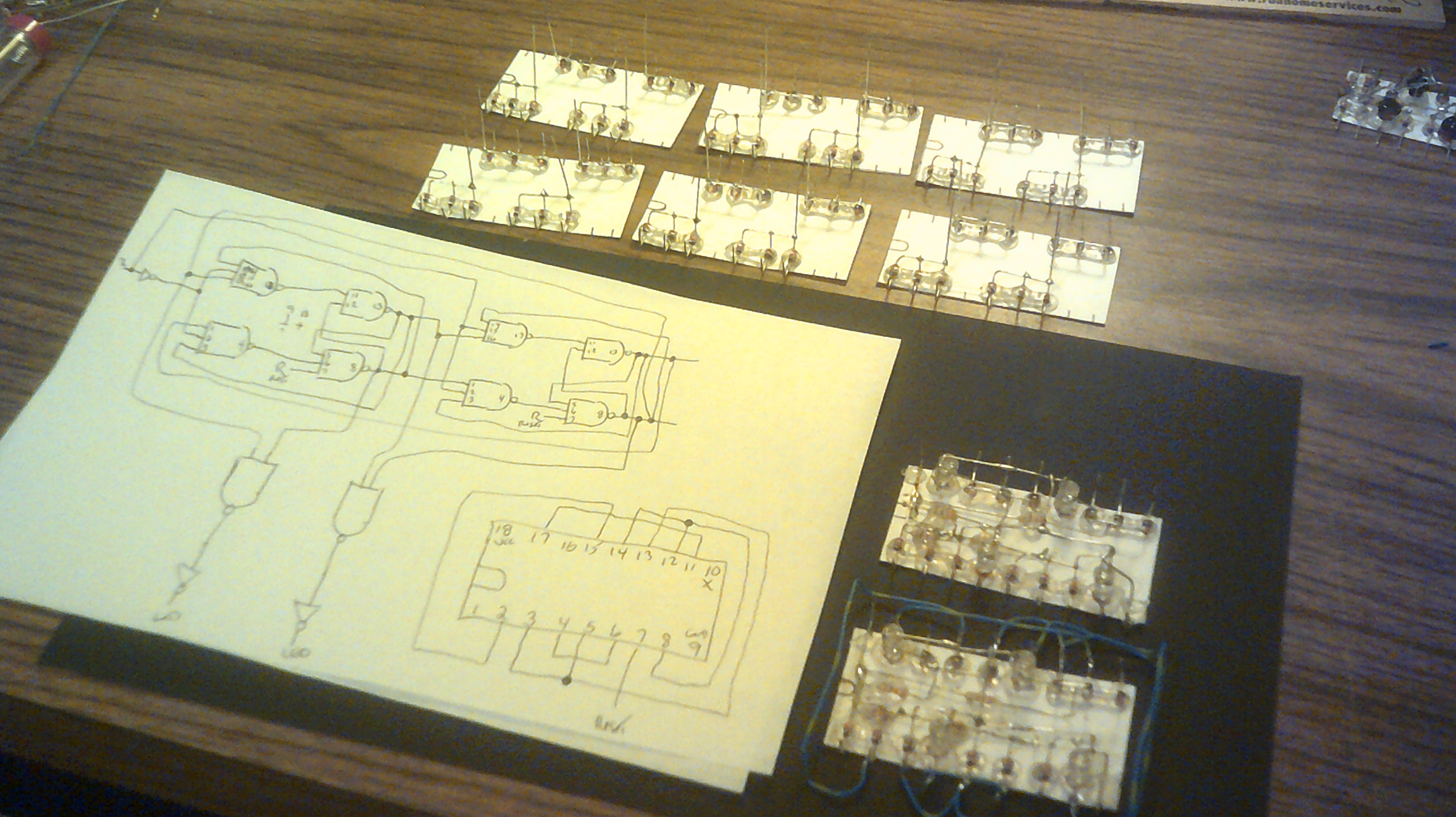
Rough layout of the gates. Top two rows are the flip-flops. The bottom two rows are the decode and invert logic.
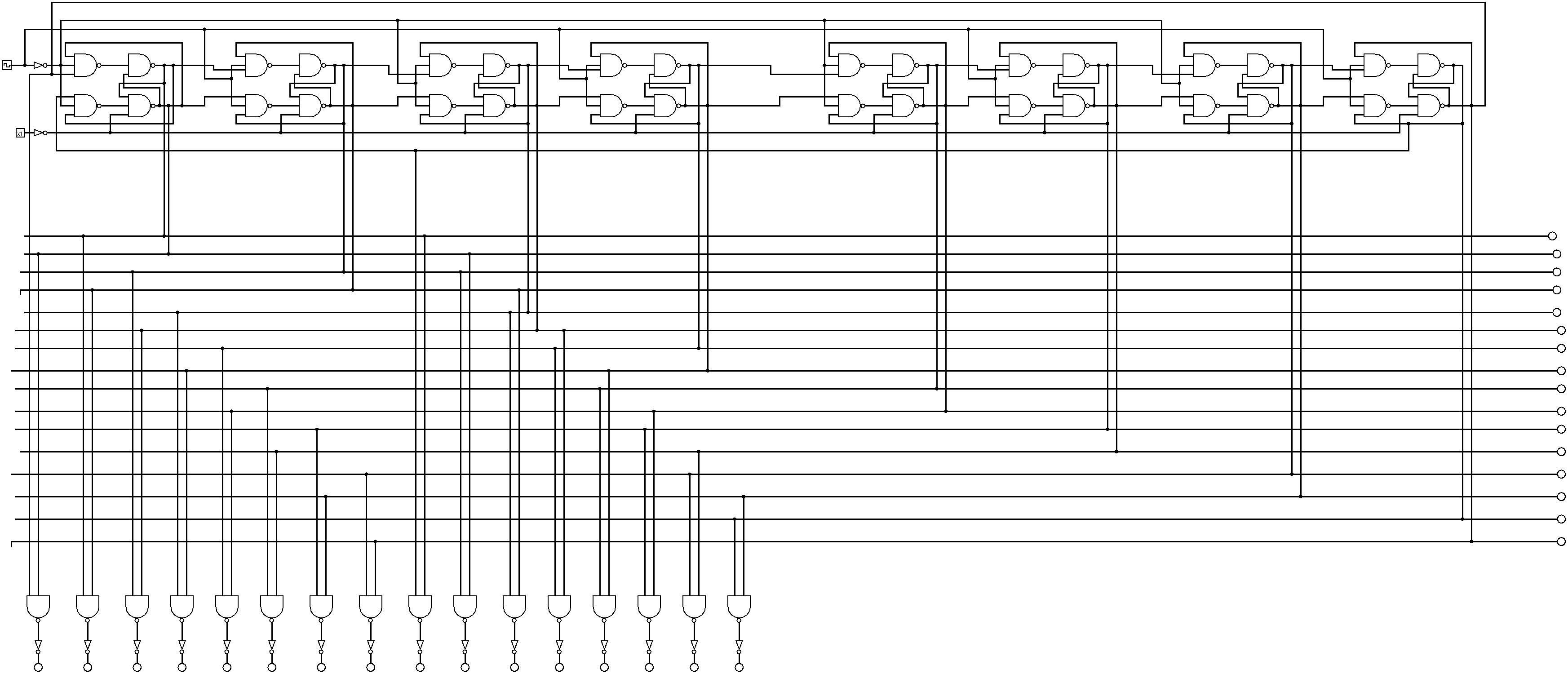
The circuit on Logisim and provided by @matseng
Discussions
Become a Hackaday.io Member
Create an account to leave a comment. Already have an account? Log In.
That's a good thought. I was thinking of going with the tried and true diode matrix but leds would have a greater cool factor for that section :-)
Are you sure? yes | no
don't waste diodes on this :-D
For each digit, output 1 line that feeds a string of LED.
Each LED of the string will light one CdS corresponding to a segment.
Several LEDs from different codes can illuminate one CdS, it's like a many-inputs OR.
I think this was done 50 years ago...
Are you sure? yes | no
A "light ROM" is quite easy to design, I think that it was used in some display modules in the 50s or 60s, but implementation is always the tricky part :-D
You could have one CdS cell for each segment, then several LED can trigger it, one LED per code.
If you use inverted logic, you can then save parts, like 50 LED instead of 70 or something like that :-)
Are you sure? yes | no