 Dr. Cockroach
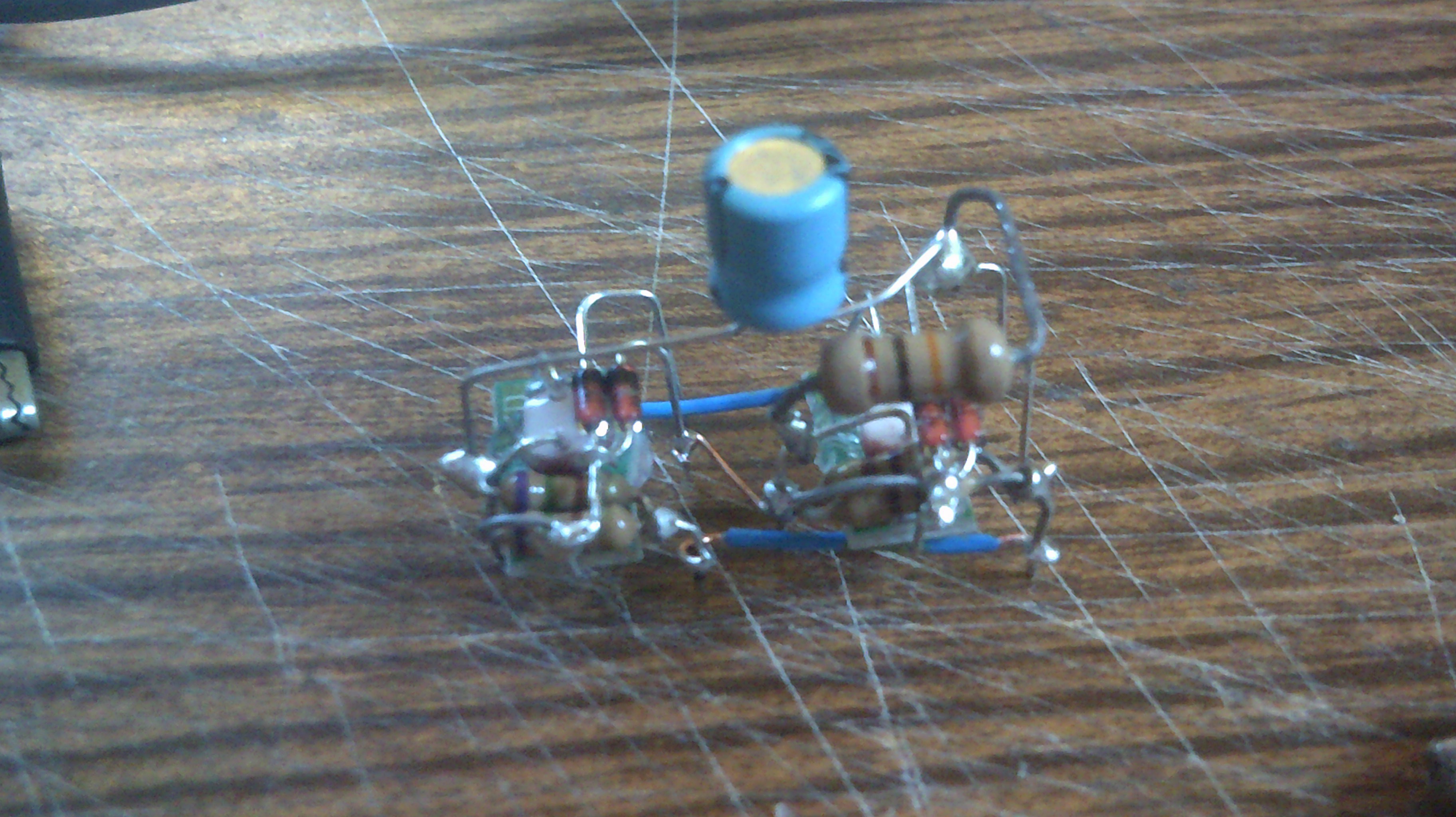
Second and more traditional circuit being tested.
Again, the video does not show very well that the clock rate is stable.
Just wired up a second astable to make sure the first was not a fluke.
Component level schematic of the final astable circuit.
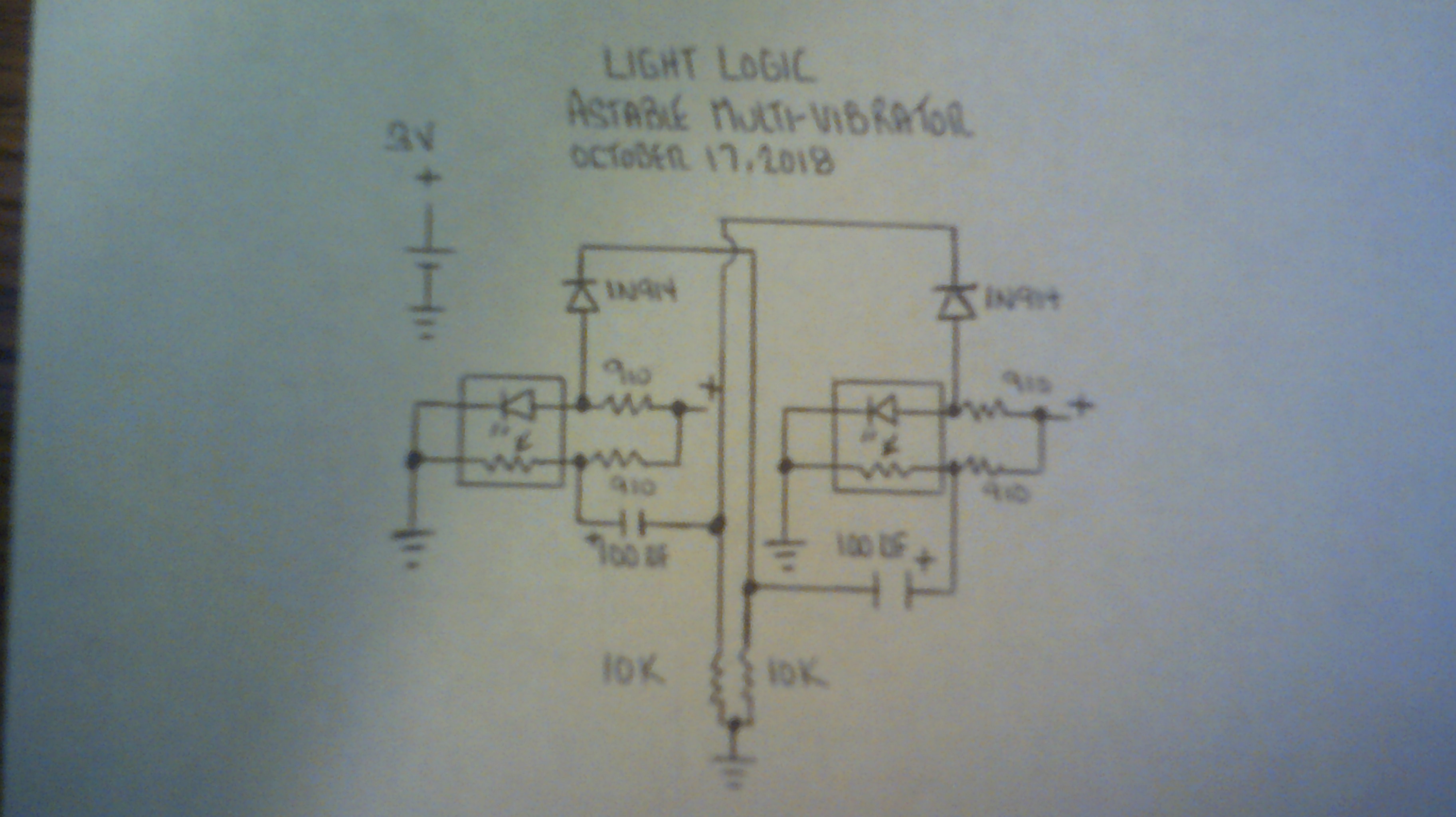

Led's D1, D2 and resistor R3 are not in this tested circuit.
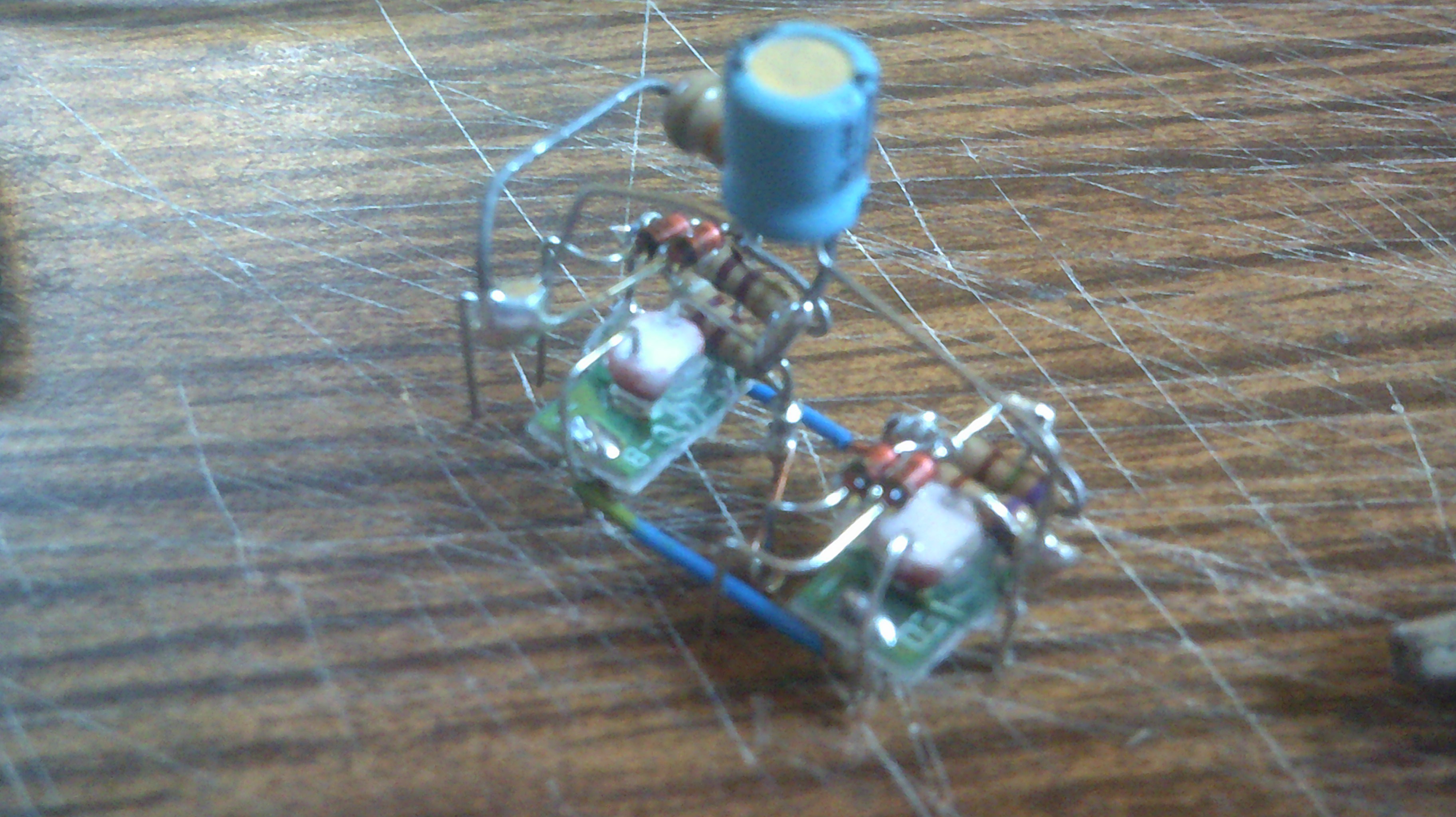
Below is the first version that was a bit messy.
First test using Light Logic Not gates wired up as a astable multivibrator. Poor video capture but the flash rate is indeed constant.
Discussions
Become a Hackaday.io Member
Create an account to leave a comment. Already have an account? Log In.