 Dr. Cockroach
I downloaded a good O-scope program for my netbook this morning and took a look at the wave forms from the astable multivibrator. Kind of expected what I saw and looking at ways to shape the wave form a little without using transistors.
As of 10/24/18 I have been able to get a almost clean square wave from the astable without transistors at 43 Hz and adjusting the voltage.
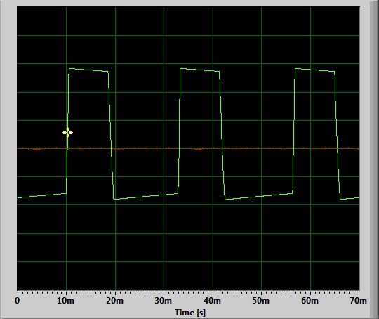
This pic is at 19.8 Hz directly from the astable.
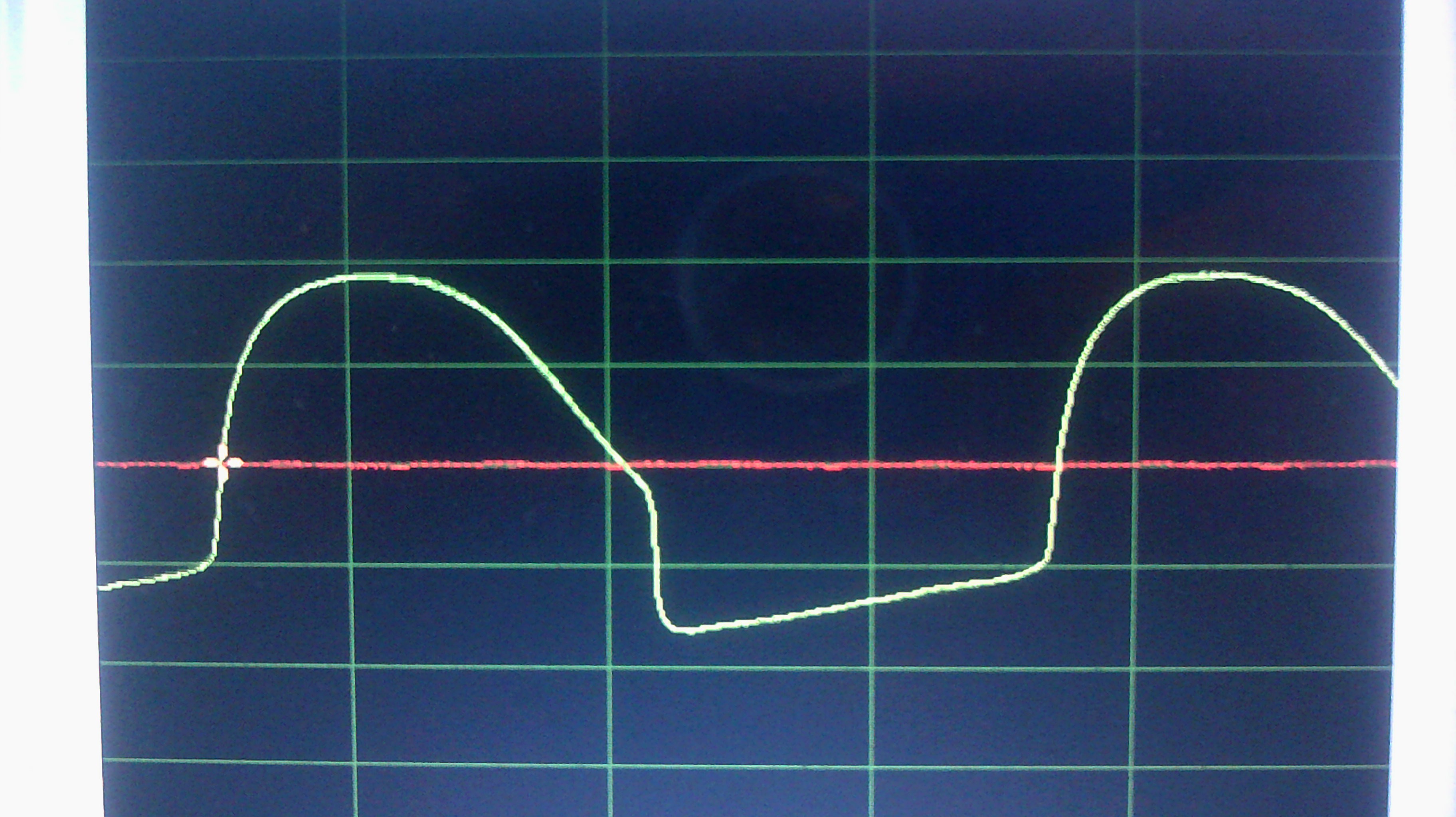
The next pic is after the clock signal has been inverted by a Light Logic Not gate.
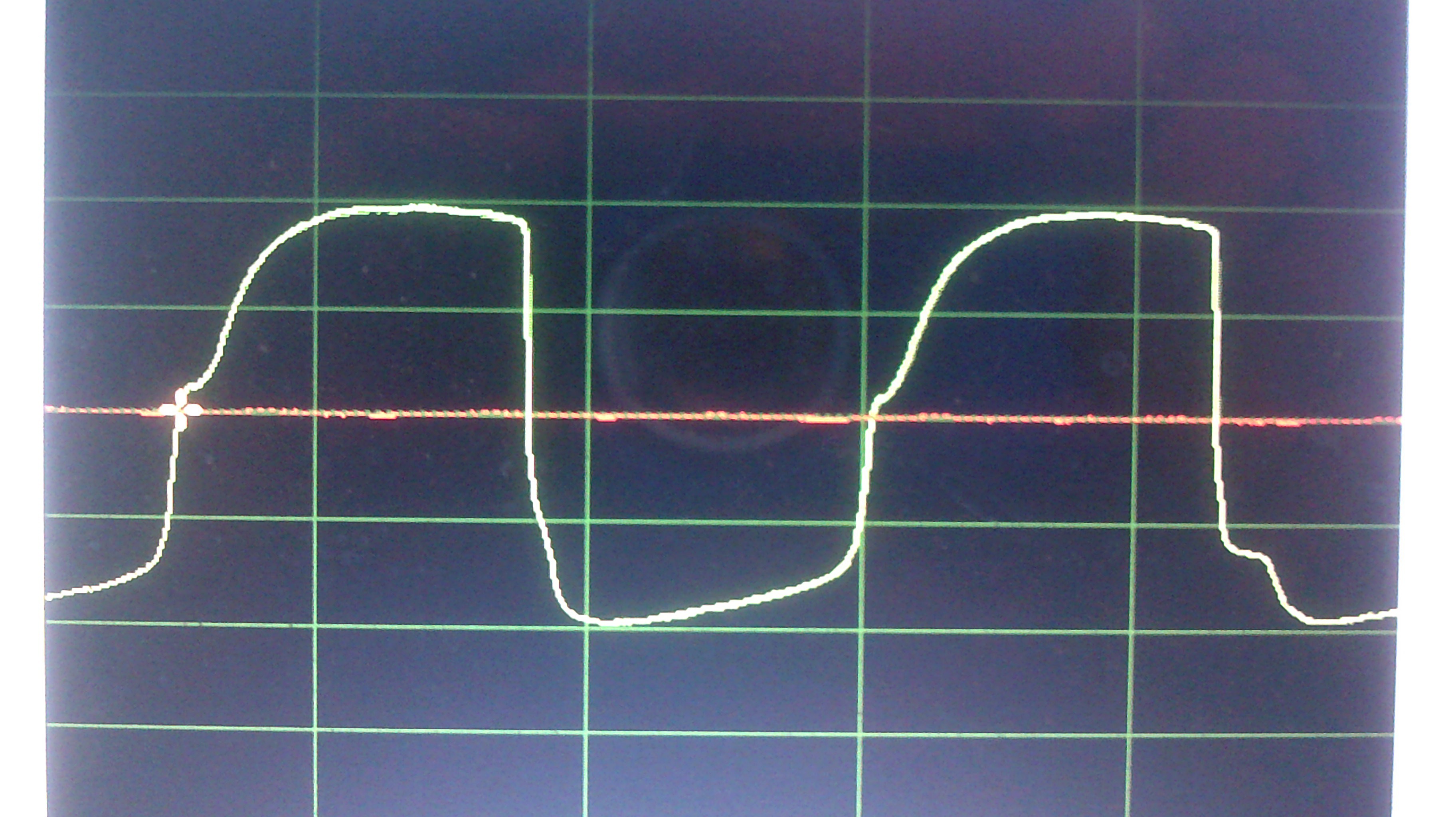
This third pic is with the frequency bumped up to the upper limit at 42.2 Hz
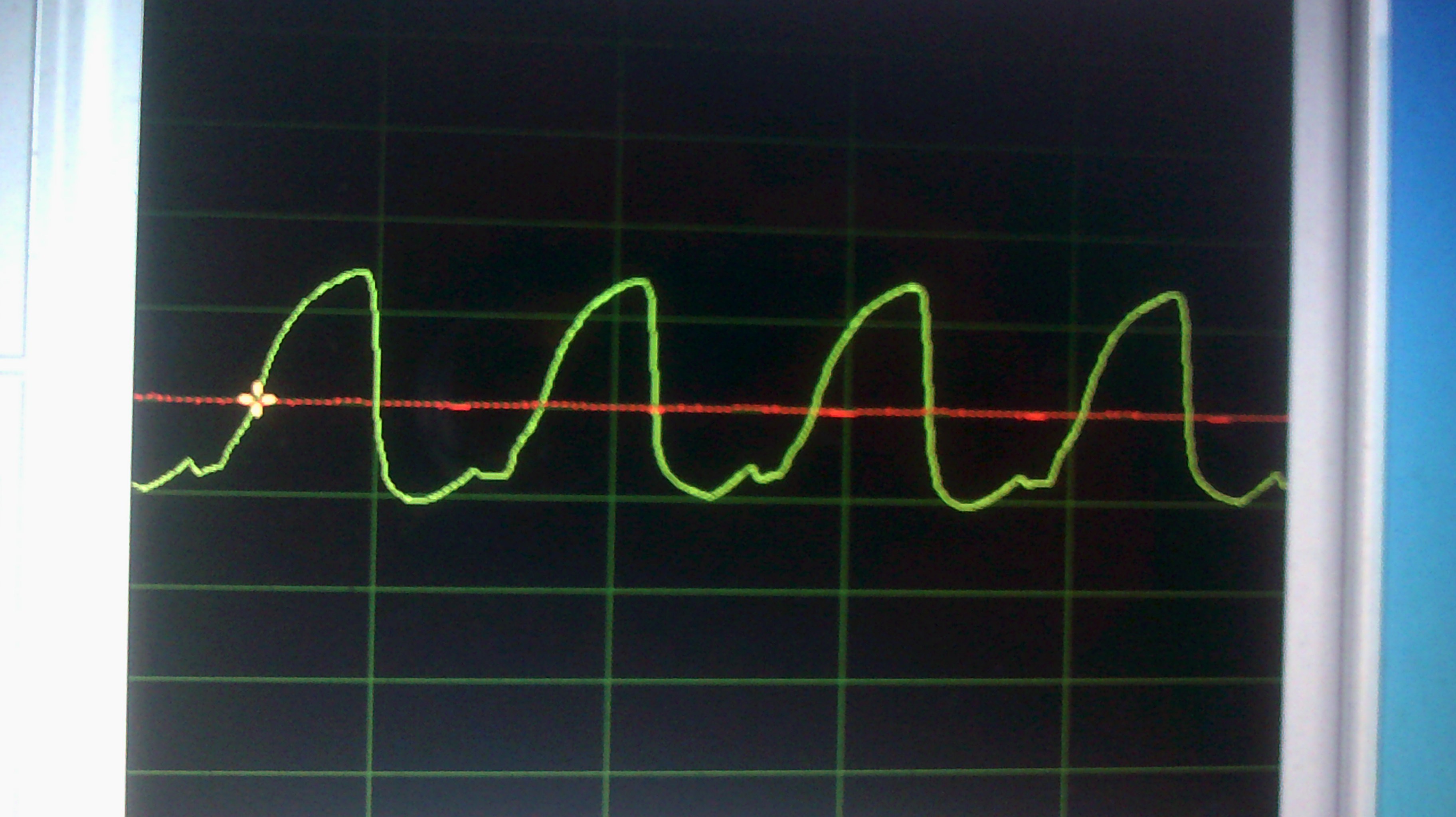
Clearly there is evidence of some capacitor action taking place in the circuit by way of the CdS internal structure. Lots of room to tinker with this circuit and looking into clamping and clipping without using transistors.
Discussions
Become a Hackaday.io Member
Create an account to leave a comment. Already have an account? Log In.