Dr. Cockroach
-
Tri-State Buffer with Diodes and Resistors
10/28/2019 at 09:43 • 0 commentsYeah, I know. All my projects on this page are using only diodes and resistors but I have to keep telling myself that.
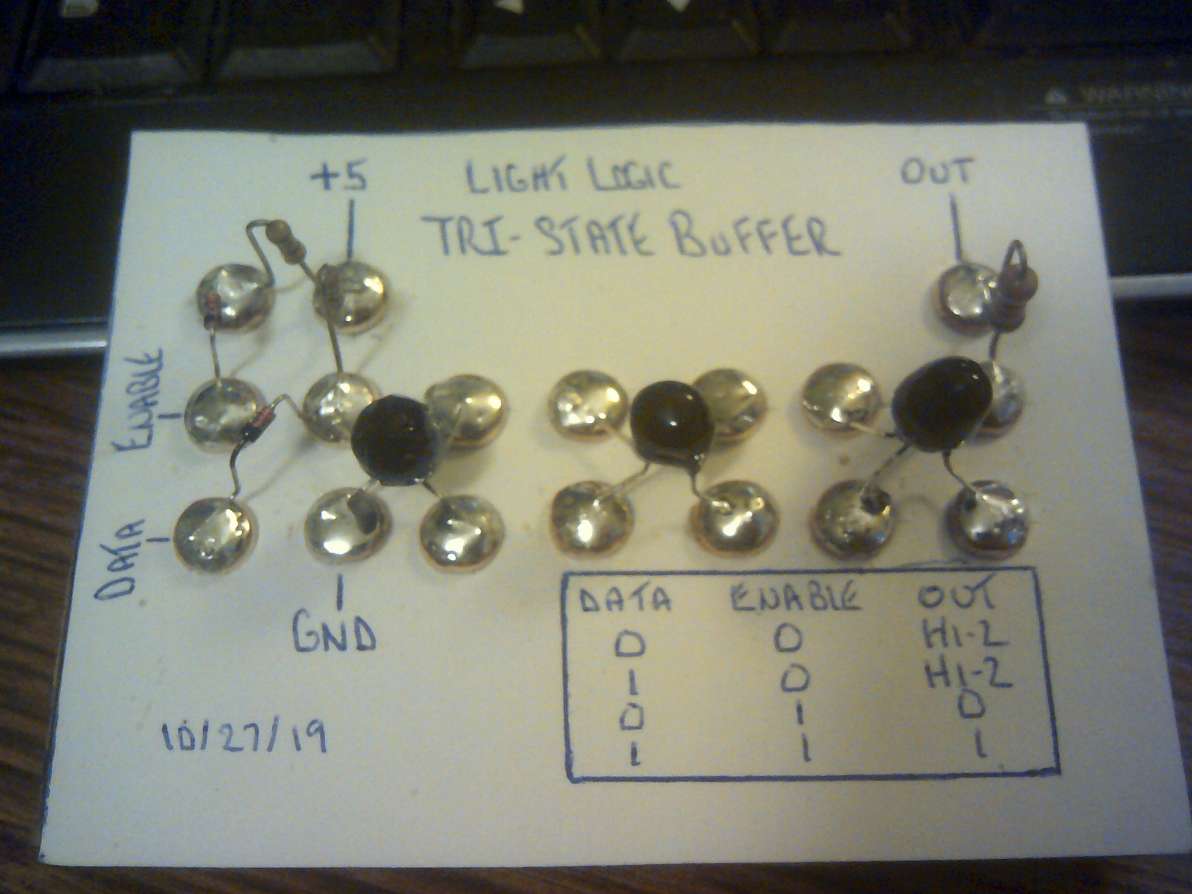
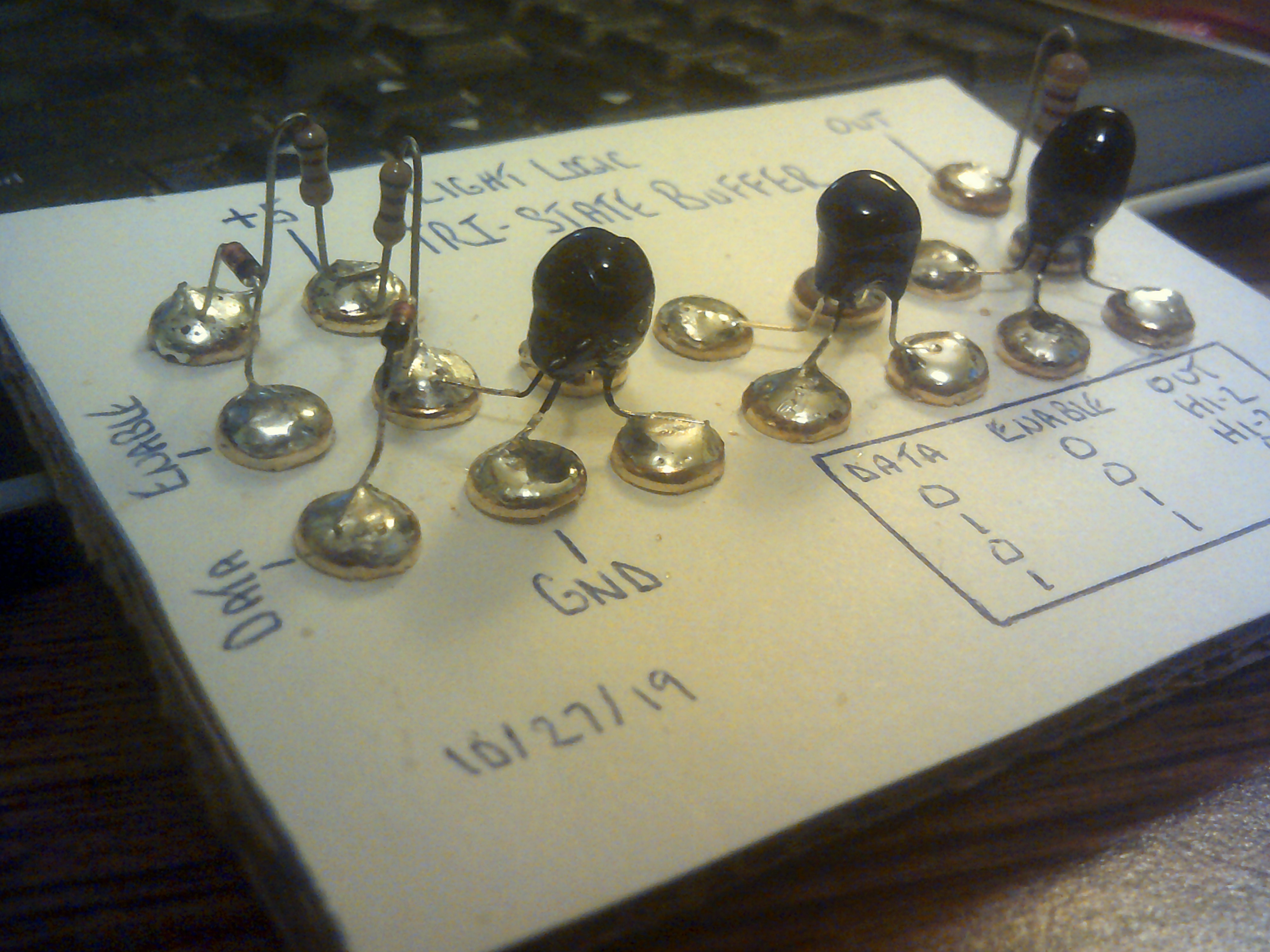
I decided to see if Light Logic would work in a Tri-State Buffer circuit intended for transistors and it actually works very nicely. No tricks used in this buffer circuit and a quick look at it will show just how basic and striped down it is. With Enable set low, the output remains Hi-Z no matter the Data setting and with Enable set High then the Data High or Low passes through just as desired.
![]()
![]()
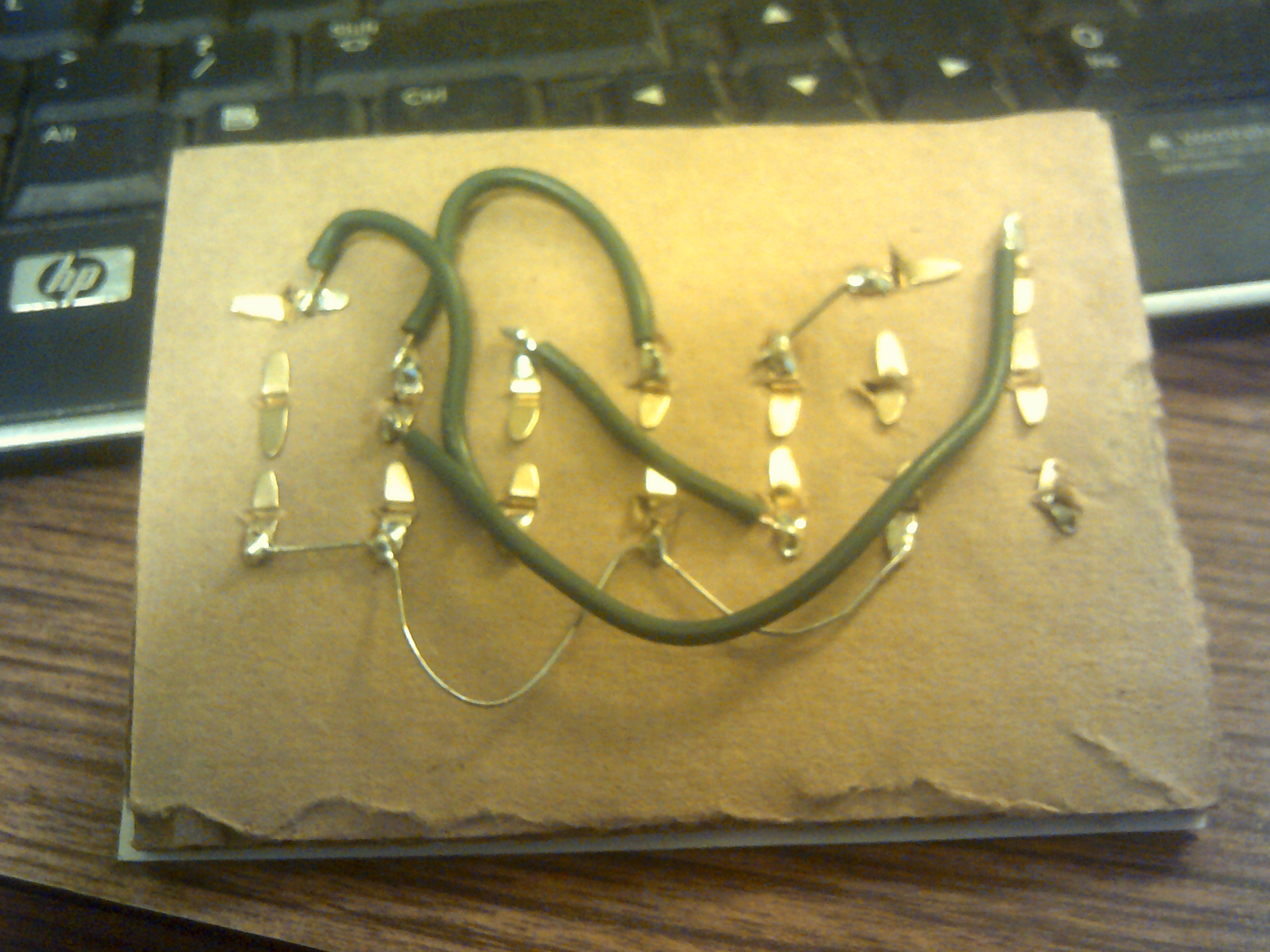
The ugly wiring on the back side.![]()
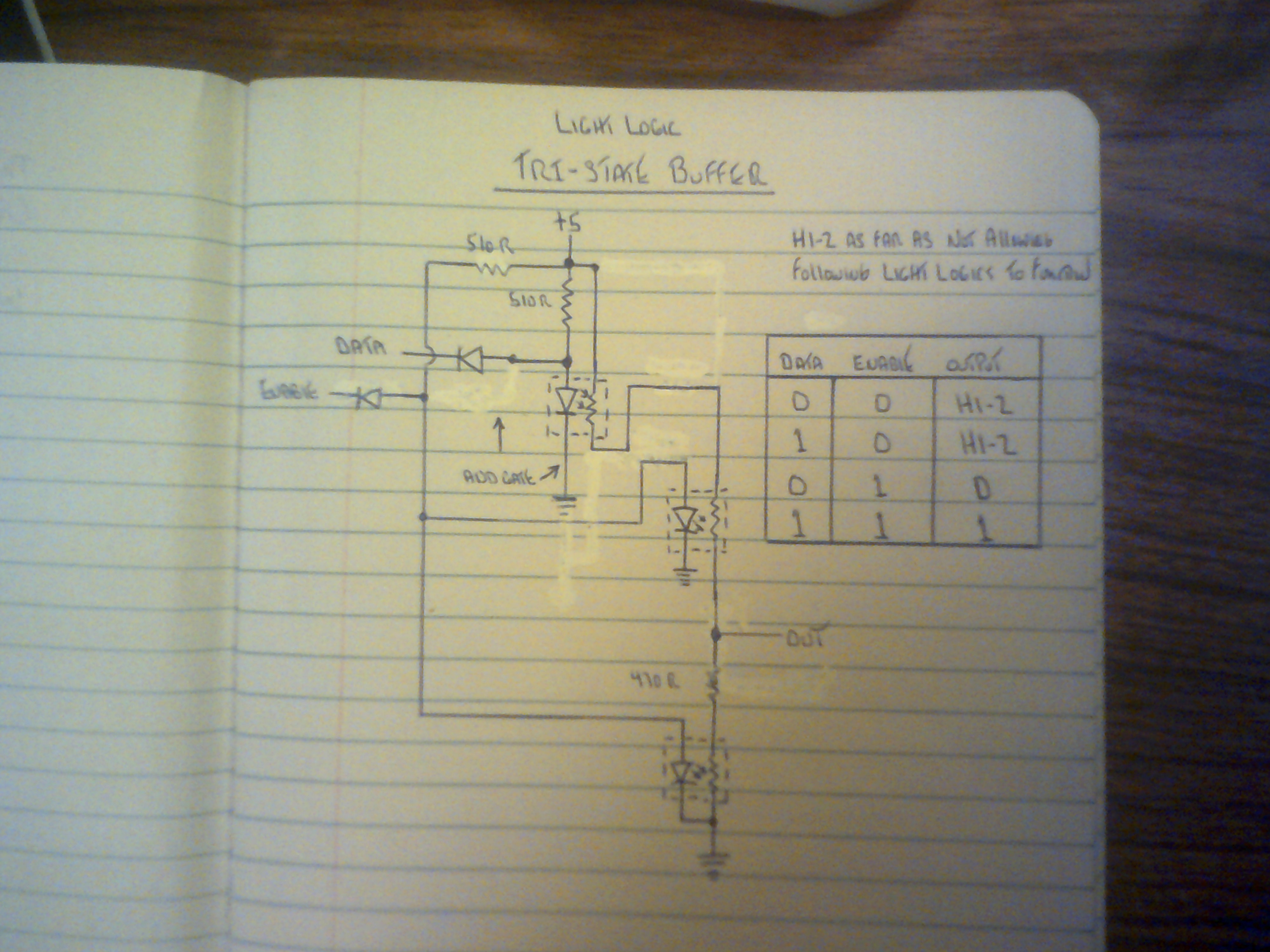
The really simple and basic circuit.
![]()
-
Latest package for Lifgt Logic
10/26/2019 at 11:24 • 0 comments![]()
This is the latest version of Light Logic or at least the Led/CdS pair. I have worked out a method of encapsulation using hot melt glue and black finger nail color that makes the placement of this component better suited to PCB and breadboard use.
The transistor used as a size reference is a 2N2222 TO-92 package and shows that my Phosistor ( Not sure of the exact name of it yet, any ideas? ) is now getting close to that level.
Also thank you Hackaday for the recent BLOG for Light Logic
https://hackaday.com/2019/10/24/light-emitting-logic-gates-built-from-scratch/
-
Sequencer with a all diode display
08/30/2019 at 00:24 • 0 commentsSept 29, 2019 - I am surprised that no one has commented about a slight quirk going on with the display. Notice that when transitioning from 6 to 7 that 8 is briefly shown. Turns out that the sequencer outputs 6 and 7 are both high at the same time for a brief moment and the display diode matrix has all leds active for that short time. This might actually turn out to be a bonus as it might assist with writing to a register much like the Cardboard Computer - IO. IO's sequencer had the same effect and came in handy.
I spent the better part of this afternoon wiring the Light Logic Sequencer to the diode display from the IO project. The display counts from 1 through 7 for this circuit and loops back to 1. Not bad considering only diodes, resistors and caps are used.
-
HIC SVNT DRACONES
08/20/2019 at 12:58 • 0 commentsHere Be Dragons - Sounds about right for Light Logic about now. I am realizing how much in uncharted waters I have become with the development of LL. The individual gates are fairly straight forward digital in and digital out but with the design and construction of the sequencer, I see analog and digital blending and twisting around into a mesmerizing light show. Is it a part of the processor I want to design and build or is it a stand alone piece of art. Or is it both, I am so confused right now. All I do know is that I must press onward into those waters and discover what is beyond. Thank you @Starhawk for the idea.
-
Things to remember if duplicating Light Logic
08/19/2019 at 14:53 • 0 commentsJust some things to think about if anyone wishes to duplicate Light Logic.
1 - There is a wide low end resistance value range with CdS photo cells so try to test and match the cells used.
2 - Stray light will kill the Light Logic effect faster than anything else. Light shielding around the Led/Ldr pair IS required.
3 - Operating voltage is very critical and selection of support resistors is somewhat trial and error.
Light Logic in its current development is still very experimental and requires a lot of hands on adjustments.
-
Sequencer Size Reduction
08/18/2019 at 22:21 • 0 commentsThis is the usable seven step sequencer for the future all Light Logic processor. Resistor and capacitor values need to be tweaked for best performance but this is working better than I had planned on in so short a time.
-
Seven Step Sequencer
08/03/2019 at 23:49 • 3 commentsThe three phase Astable is now a seven step sequencer. When wired in order 1,2,3,4,5,6,7 the firing order is 1,6,4,2,7,5,3 then returns to 1 so it steps by 5. The sequence does repeat. This can be the sequencer and clock combined for IO2 the Inside Out Light Logic computer. No other clock will be needed.
Here is a good display of the sequencer in action and I realized that I now have a solid clock and sequencer in a single circuit. This will be used for the Light Logic computer project this winter.
I ran out of ideas other than adding a starter switch to the panel. On power up the loop freezes so I have to ground one input in order to unbalance the loop. Then I got the scope out and then the music fits the display.
That is a trace of cell one followed by cell six.
After I looked at the output traces, I wanted to see if I could sharpen them up a bit. so I added a Light Logic non-inverting buffer gate to the output of cell number one and the next video clip shows a big improvement. The lower trace is output number one and the top trace is the same output run through the buffer.
-
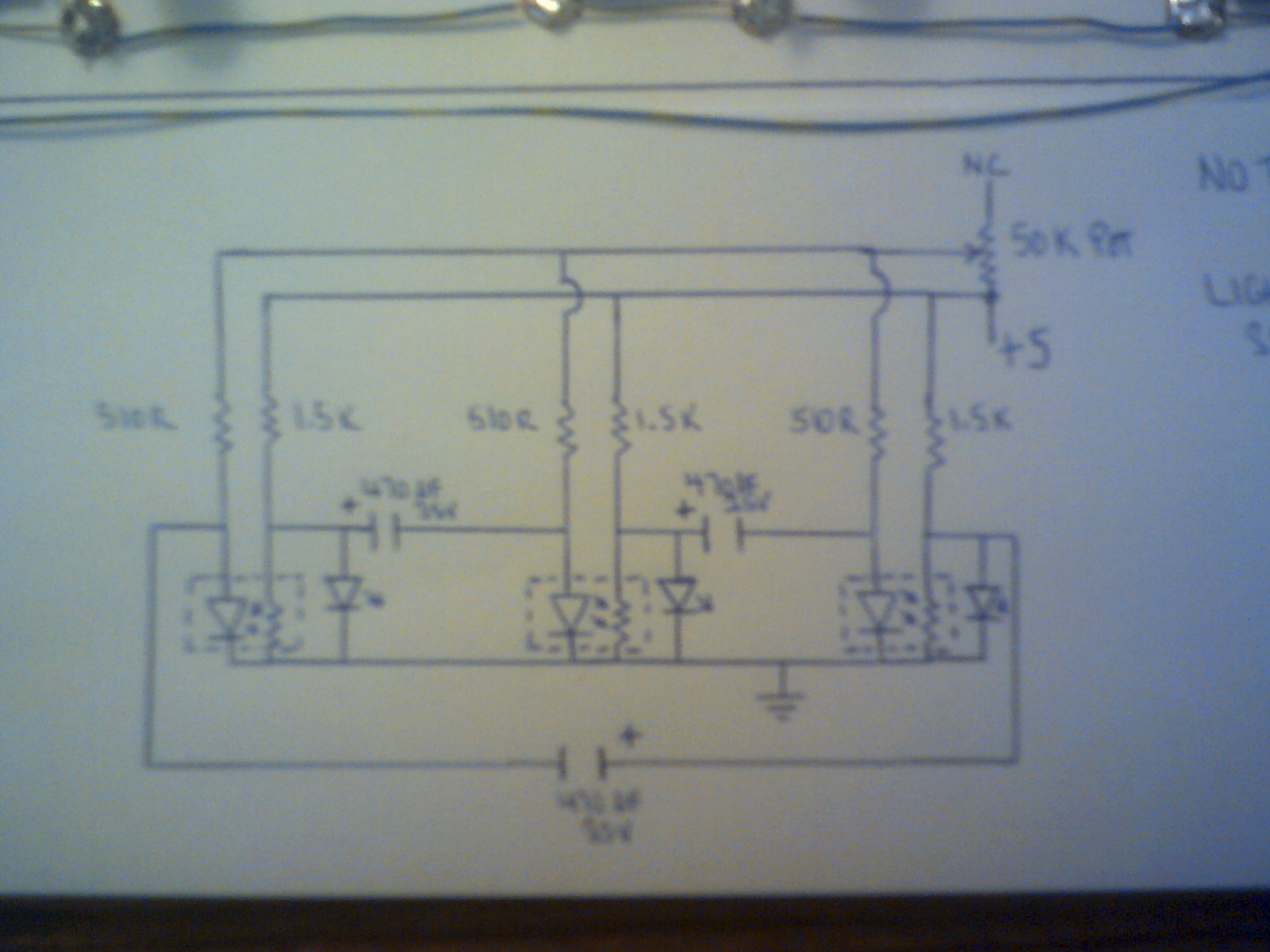
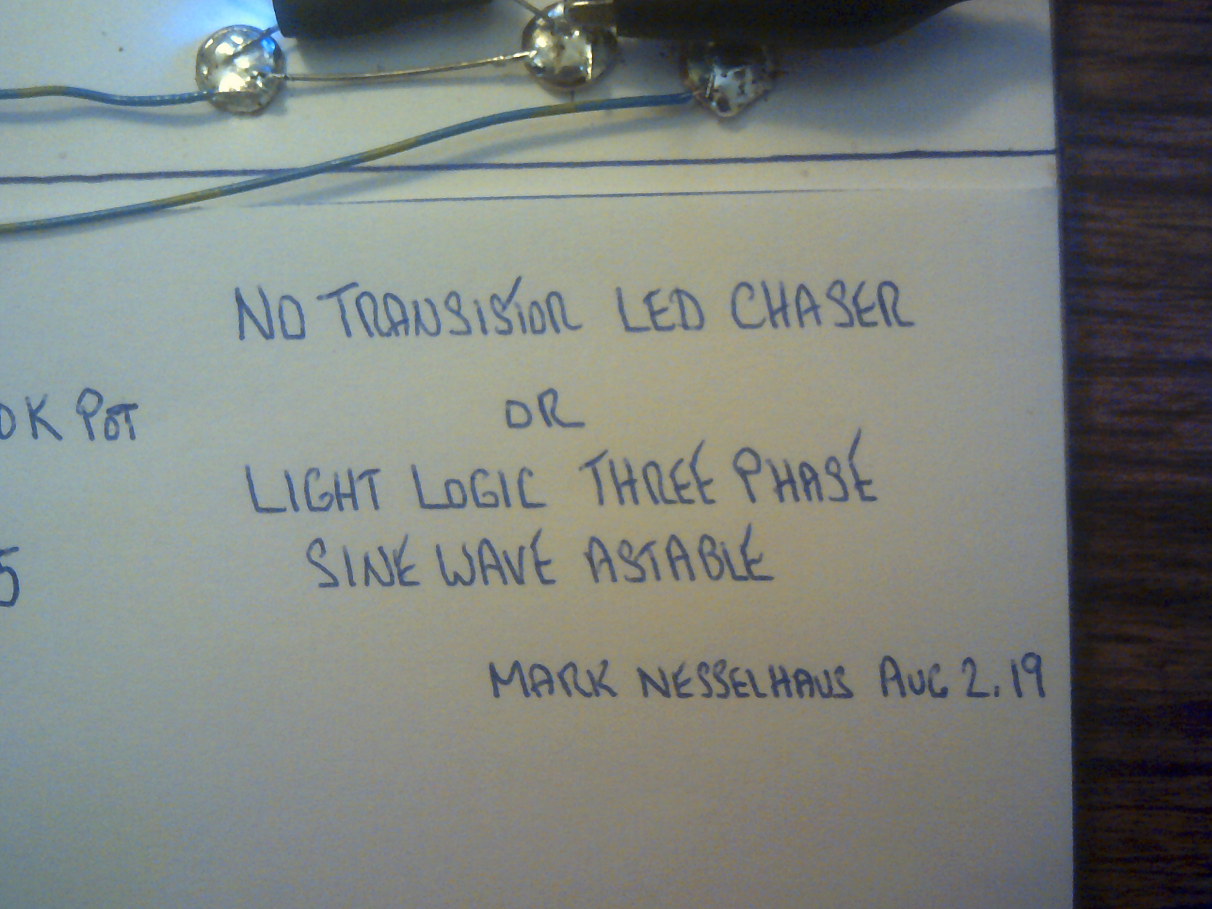
A No Transistor 3 Phase Astable ????
08/02/2019 at 15:55 • 0 commentsThis circuit is so cool to look at while running and took me the better part of a week to figure out. The goal was to make a LED Chaser using Light Logic and I am pleased with the result to this point.
![]()
![]()
I have looked at the signals with my scope and indeed it is outputting what looks like smooth sine waves.
-
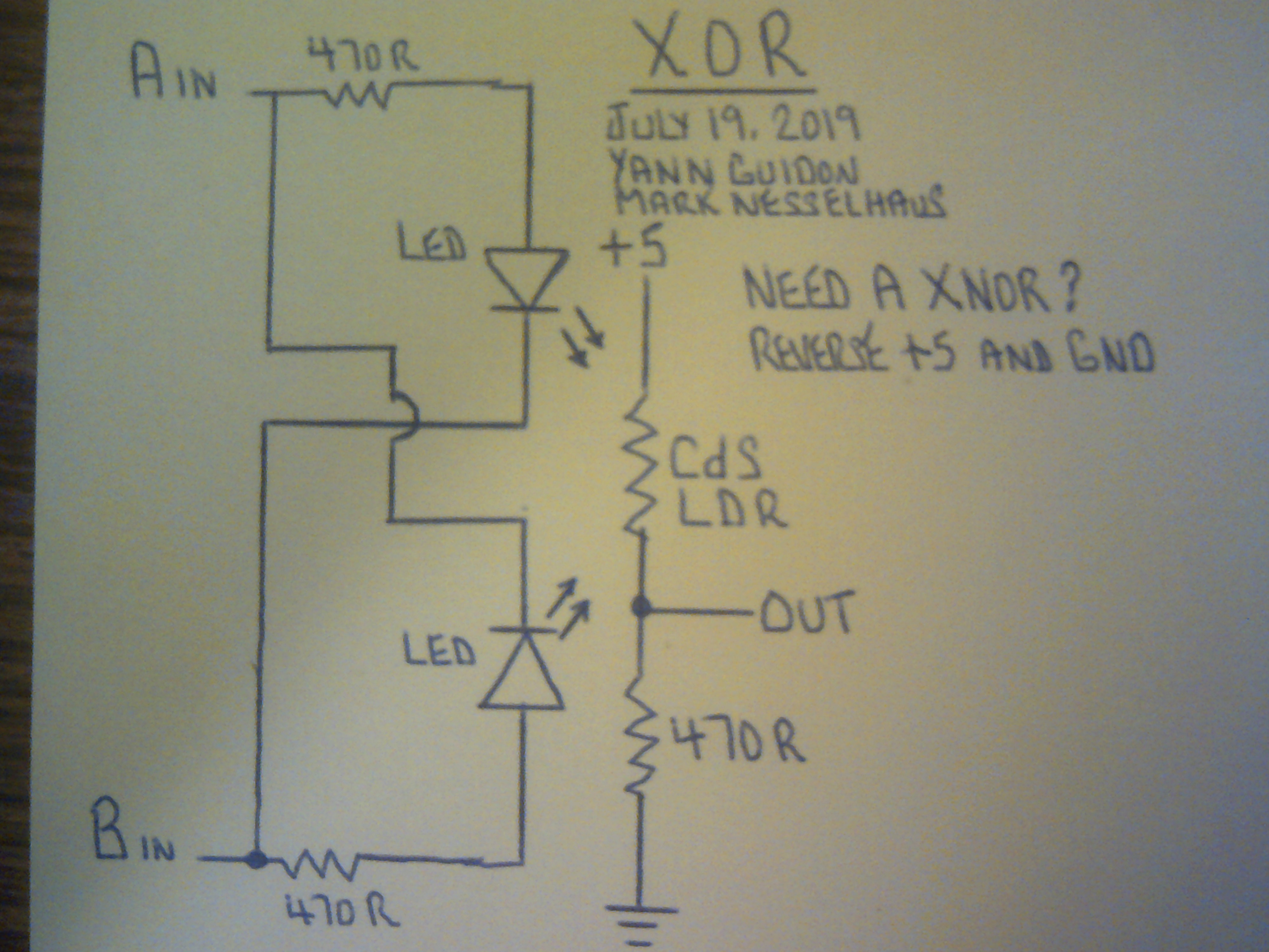
Another simple XOR that works
07/20/2019 at 09:17 • 6 commentsHere is another XOR circuit that I wired and tested last night. Thanks to Yann Guidon for this idea as it does further reduce the parts count. The Input resistors are optional depending on the logic level voltage. For a XNOR, just reverse the +5 and ground. This XOR, once again, has good solid logic levels on the output.
![]()
![]()
-
XOR and XNOR simple as ever
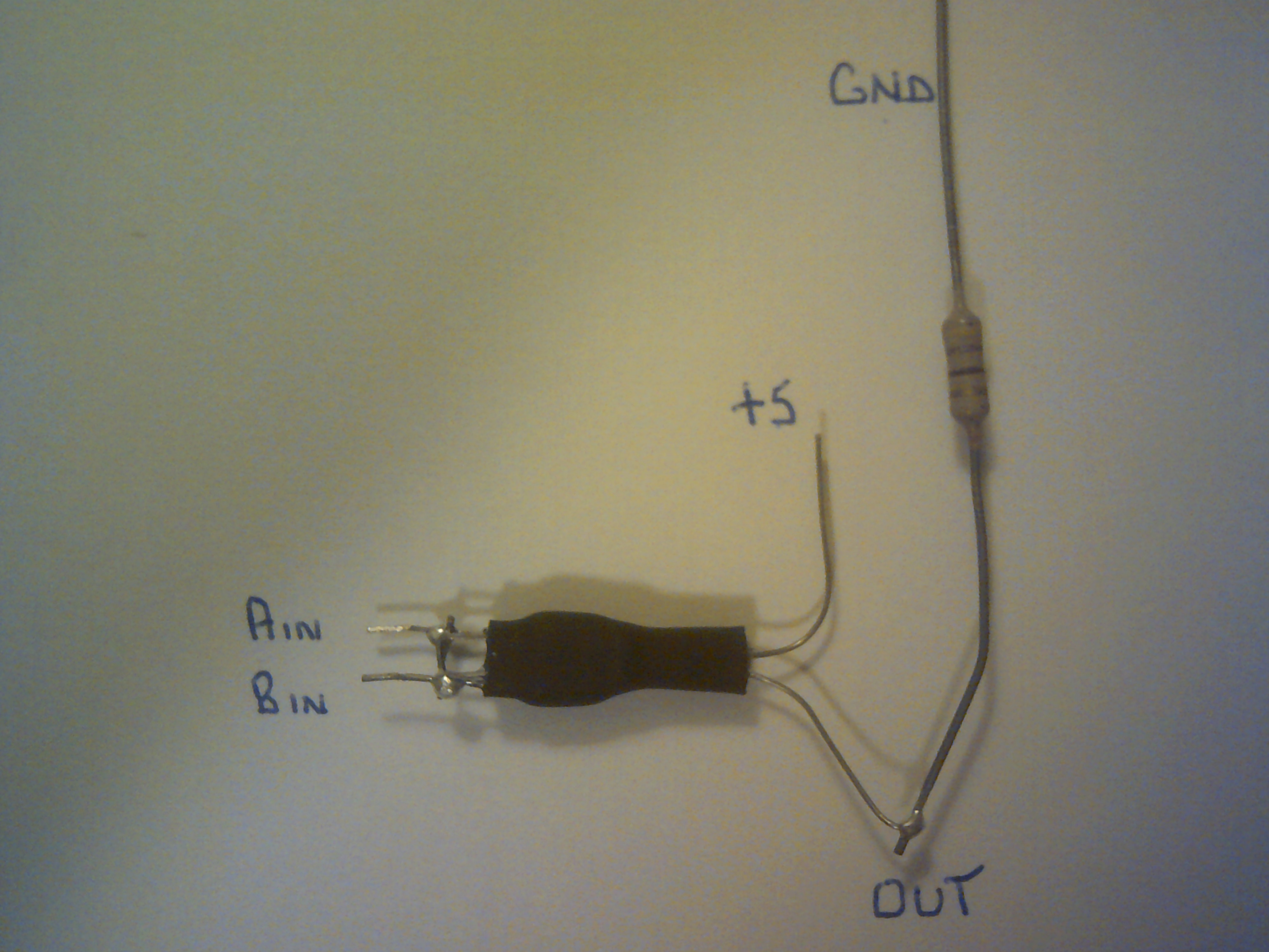
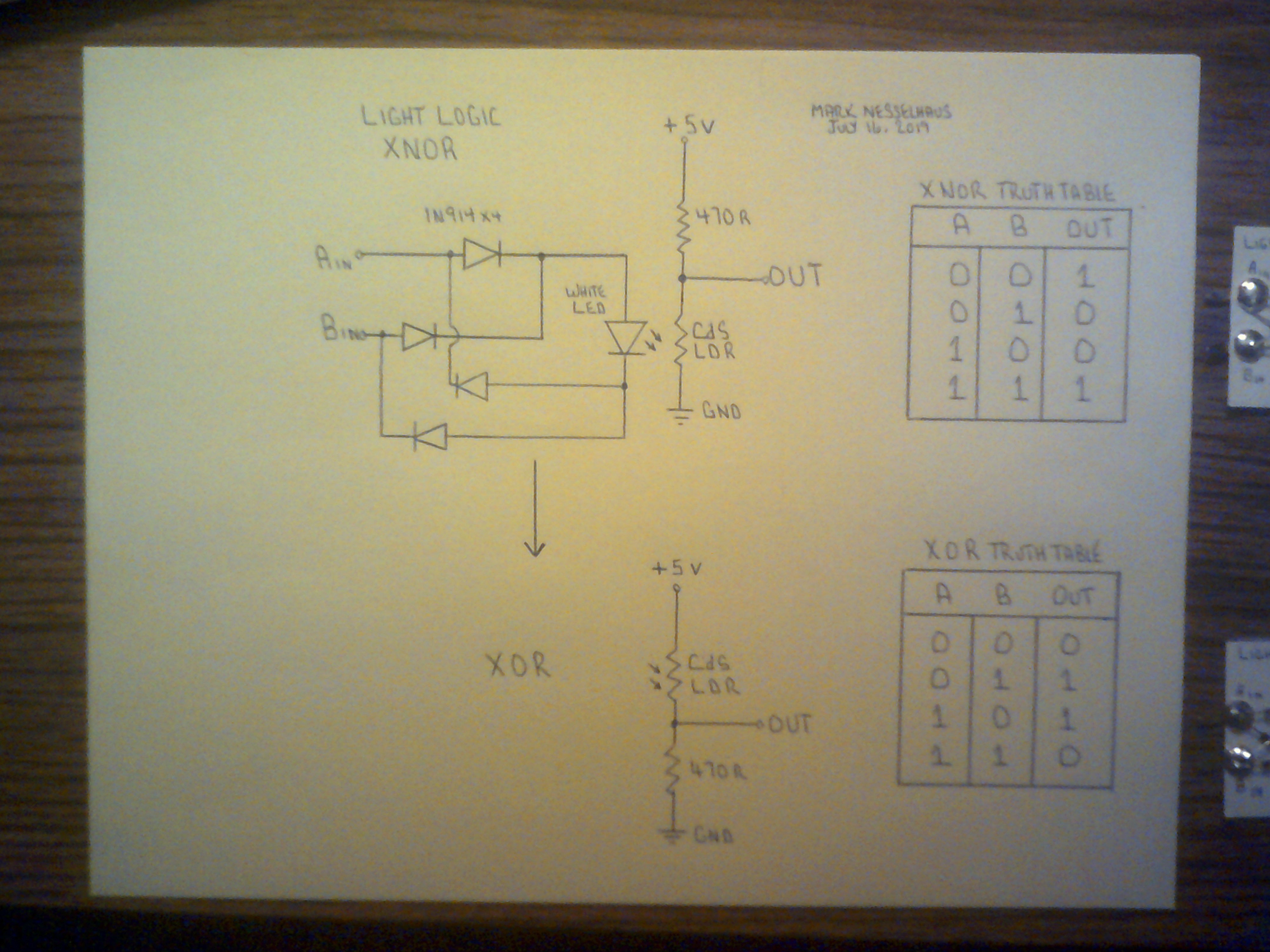
07/16/2019 at 10:01 • 2 commentsI now have, thanks to @Starhawk for the nudge, managed to create A XOR and XNOR gate that uses just a single Light Logic switch. I no longer need to combine other gates for these logic functions. Logic highs are 4 volts or higher and the low levels are less than 0.5 Volts. Good enough to be used with the rest of the Light Logic family.
![]()
![]()
LIGHT LOGIC - HIC SVNT DRACONES
Using a LED/LDR pair to form inverting Photonic logic gates. The entire Boolean logic set handled by resistors and diodes! Who'd'a thunk