 Timo Birnschein
I like bread boards. For some reason, my father was never a fan and rather created his own rapid prototyping system which required lots of soldering wires to little shoes and pins instead of just plugging in some single strand wire into a hole. Now that I use bread boards, I really don't understand why he went that route anymore. But that's ok.
I created the first version of my remote on a bread board. This was also the first version I showed Acton in person (Thanks Peter!). To my surprise, they were very open to me reverse engineering their controller - but as it happens, the industrial design is theirs, the logic and the schematics are essentially the standard remote everybody gets when buying a skateboard using these motor controllers. At least they put their own spin on it - even though not with the best of components.
The schematics are as easy as they can get.
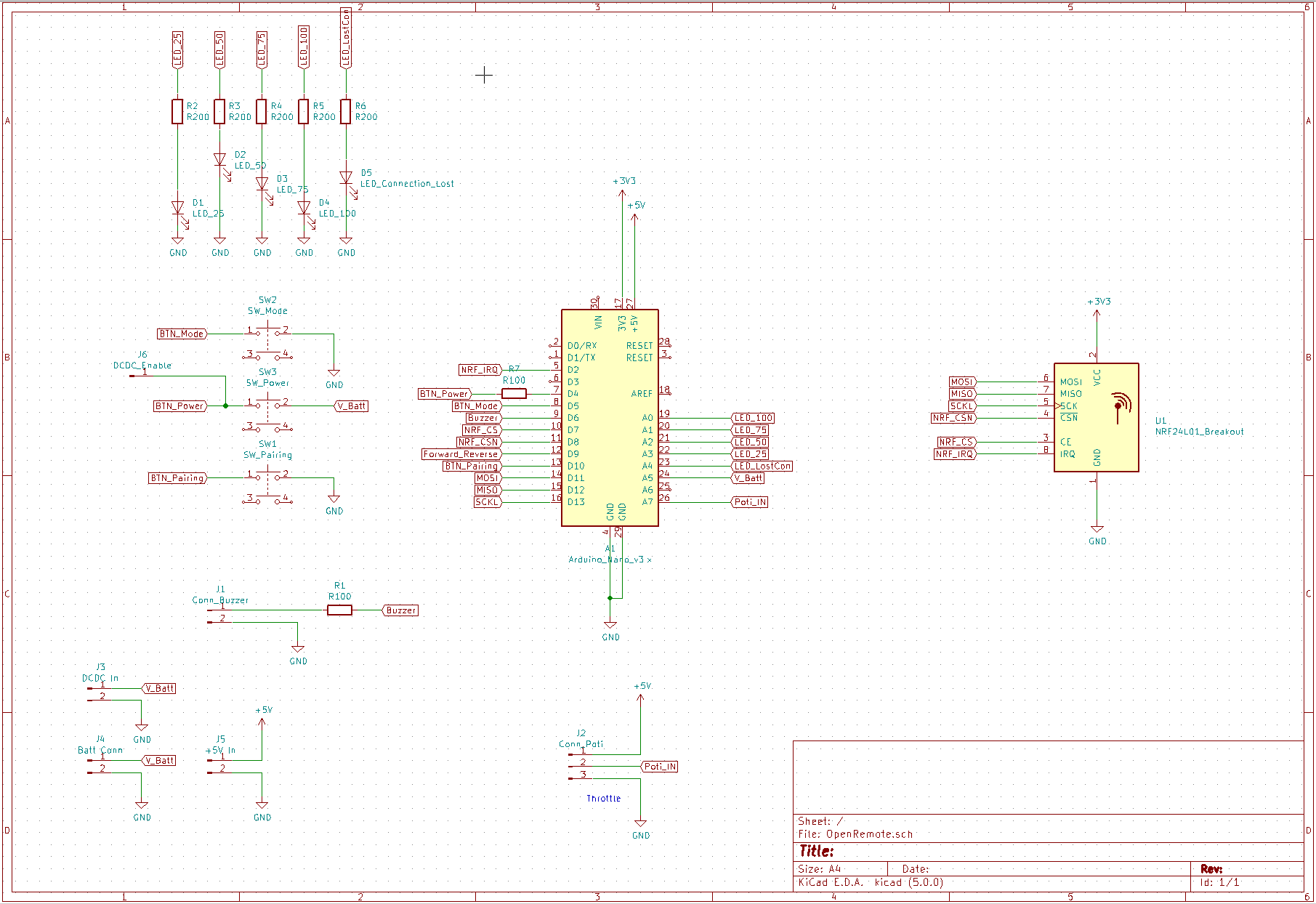
- Arduino Nano
- NRF24L01+ Breakout Board
- 2.5-3V to 5V DC/DC Converter Board
- 5 LEDs in different colors with their corresponding resistors
- 3 Micro Switches
- 1 Buzzer
- 1 Potentiometer for the Throttle
- 1 Power Switch
- 2 AAA batteries instead of a LiPo with additional charging circuit
That's it. It requires nothing else. I sense the real battery voltage using A5 on the Arduino by plugging it in directly. If the voltage goes too low, I cut the throttle and only allow braking - analogue to what the Acton controller also does. I liked that as the controller still works but it only let's you stop safely.
I also use AAA batteries because they can be obtained everywhere and spares can be easily kept in a pocket or a backpack. I do not follow the rechargeable battery philosophy for the remote as it lasts me forever.
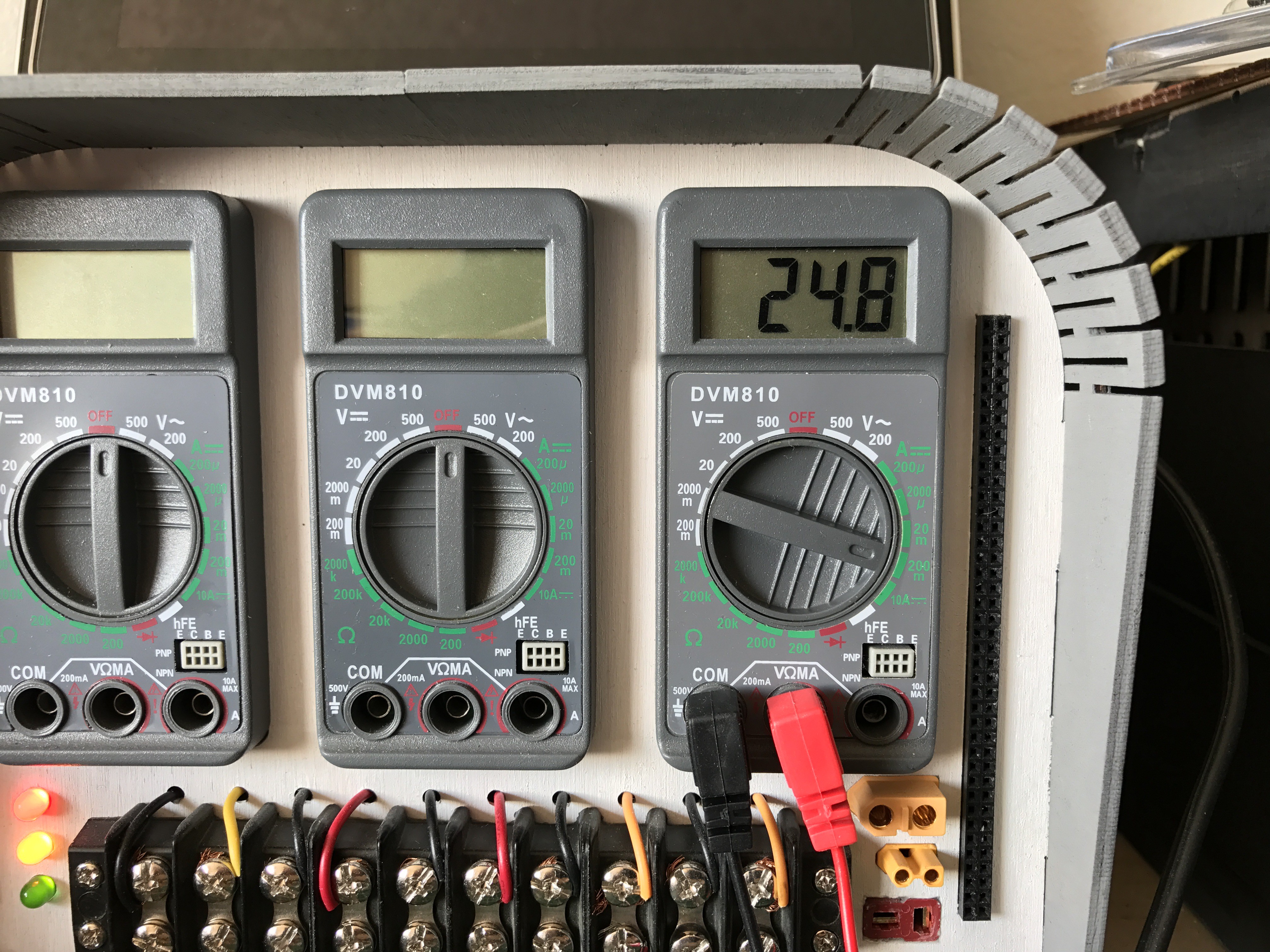
I have an average power consumption of 25mA and considering the batteries have about 1000mA, I can drive for 40h(!!) before I need to swap batteries. Even if I consider 20% reserve, it's still massive!
The layout is also pretty straight forward. Although, I went with a completely custom shape that fits straight into the 3D printed part! I did this by creating the board shape in Solidworks, then exporting it as DXF, then importing it into KiCAD, and then start the layout with the DXF on the Edge.Cuts layer. This works great!
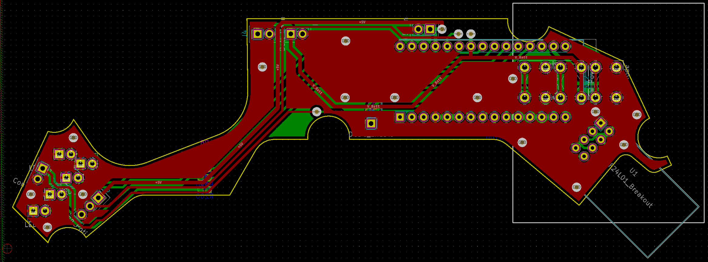
My only constraint was, I wanted to use my own PCB mill to fabricate the PCB. In order to do that, I needed to keep the trace thickness above 10mill, and the holes at around 0.8mm and 0.9mm for the different parts and vias to avoid the need to manually swap the tool all the time or accidentally cut the traces or restrings to shreds.
To machine the board, I used a China V shaped endmill with 0.2mm tip - but since the endmills came with varying quality, I used the one with the smallest possible tip shape of about 0.1mm. Not great in terms of quality but great because I could mill smaller traces.
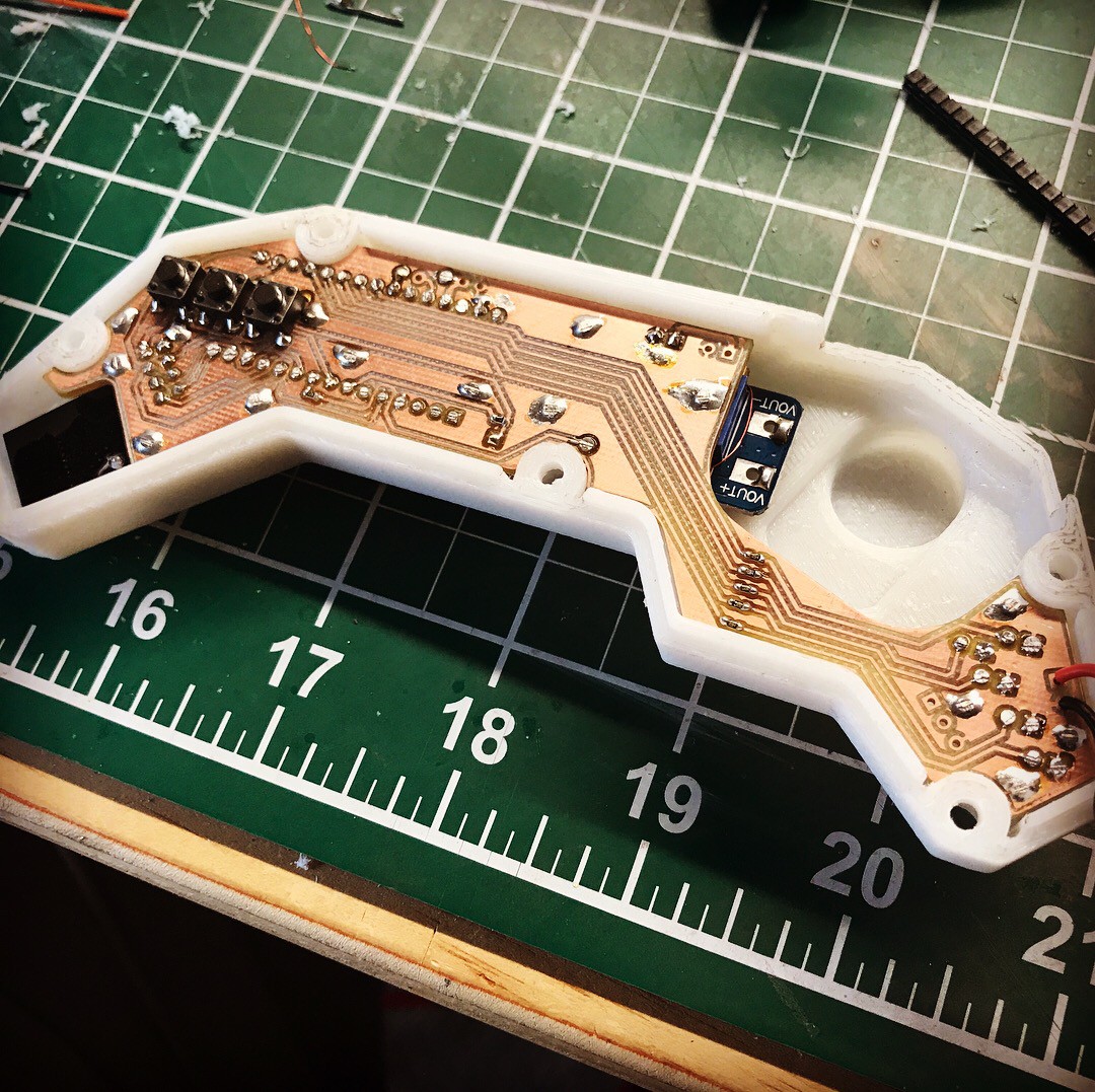
In the end, I realized I forgot about the power switch in my enclosure design so I needed to drill two holes and file it to a rectangle to make it fit.
Connecting all the wired parts was a bit of a pain. There is not too much space in there to work with and the flying wires got caught everywhere. In the end, I went with thin magnet wire for almost everything that I secured with some hot glue where necessary.
I really like this design and was blown away by how well everything went together. Being able to create a custom shaped board like that at home was crazy cool and seeing it just slide into the 3D printed part was immesely satisfying!
Discussions
Become a Hackaday.io Member
Create an account to leave a comment. Already have an account? Log In.