 Silícios Lab
Presentation of the Project
Following, I'll introduce you to the full explanation of how to develop your own Standalone Arduino on the breadboard.
Introduction
In many projects with Arduino, the people needs implement the project in a PCB Board, but don't know how to construct a circuit with few components, for mount a similar arduino, also known as Standalone Arduino. One other cause for people use the Standalone Arduino is because using the Arduino Board, the project will have greater financial value.
Therefore, in the article, I'll present how to construct a Standalone Arduino in a Breadboard, for easy your project construction.
The Project
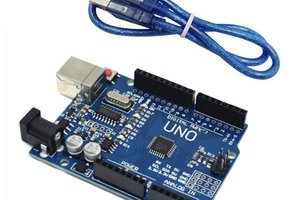
In this project I will use the Arduino Uno as programmer to transfer the code of PC for Atmega328 Chip.
In the Figure 1 is presented the basic circuit for mount the standalone arduino. Each component of circuit is essential for correct working of standalone arduino.
The pin 1 is responsible for reset of chip and of our application, consequently. The 9 and 10 pin are used for clock circuit. Witouth the components (crystal and ceramic capacitor), don't is possible occur the code execution in real time.

Figure 1 - Electronic Schematic of Standalone Arduino.
The pins 7, 8, 20 and 22 are the power supply pins for the CHIP Atmega328P.
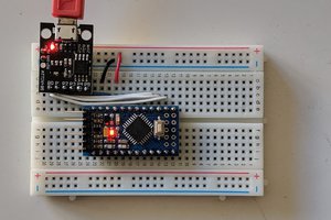
According with the electronic schematic, was mounted the circuit on the breadboard, as is presented on the Figure 2.

Figure 2 - Circuit of Standalone Arduino mounted on the Proboard.
In the video 1, I've presented this circuit mounted in a breadboard.
Programming the Atmega328P
For realize the programming process of simple form you can use the USB-TTL converters or you can use the your own arduino. In this article, I use the arduino uno for facilitate the programming process as is shown if Figure 3.

Figure 3 - Arduino Uno for programming the Atmega328P.
Firstly, remove the CHIP atmega328P and connect it on the Breadboard.As is possible see, is need you connect the reset pin of arduino UNO in the reset pin of the Atmega328P. Connect the RX of Arduino on the pin 2 of Atmega328P. Connect the TX of Arduino on the pin 3 of Atmega328P.
For transfer the code of the Arduino IDE for the ATMEGA328P CHIP is of same form you transfer the code for arduino board. Don't need change none parameter on the arduino IDE.
By following these steps, you will be able to apply arduino to your projects and develop your PCBs using standalone arduino.
Acknowledgments
The Silícios Lab thanks PCBWay for its support and work together.
In addition to them, the Silícios Lab thanks UTSOURCE for its support, for offering us the low cost electronic components of great quality and good service.

 Arduino KIT
 deqing
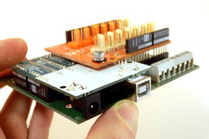
 Hartmut Wendt
I liked the first part of the tutorial. I didn't quite understand the last part, about programming the chip. What is achieved by removing the chip from Arduino and mounting it on a breadboard?
As far as I know, if you start with a blank (not programmed) ATmega328P, like I assume we're doing here, it can't be programmed via USB-TTL until it is flashed with a bootloader. This can be done using ISP (in-system programming), using an AVR programmer (USBASP, USBtinyISP) or an Arduino flashed with the ArduinoISP sketch, and it's ICSP header connected to the right pins of the chip to be programmed. When the chip has the bootloader, it can be programmed using a USB-TTL converter. Bootloader is actually optional, the actual firmware can be just flashed using ISP. If done like this, ISP will need to be used every time for re-programming. You will have more flash memory available for your program, and the board will boot up faster on reset.