Close
0%
0%

Data Logger

A simple and extensible data logger with Bluetooth

Similar projects worth following
This is a crude data logger that uses the Microchip PIC16F1769 8-bit MCU. Instead of on-board memory or a wired connection it uses Bluetooth SPP to send data. It can capture both binary and analog events and uses a simple command interface for configuration via a terminal emulator.

You add your own circuitry to interface to its inputs. The logger can also set an output pin high based on an analog event. Event records can be sent in ASCII or binary mode for additional processing on the receiving device.

I designed this some time ago out of necessity for testing another project.  I needed something that could run for extended periods and accurately capture events.  It's designed to be simple but extensible.

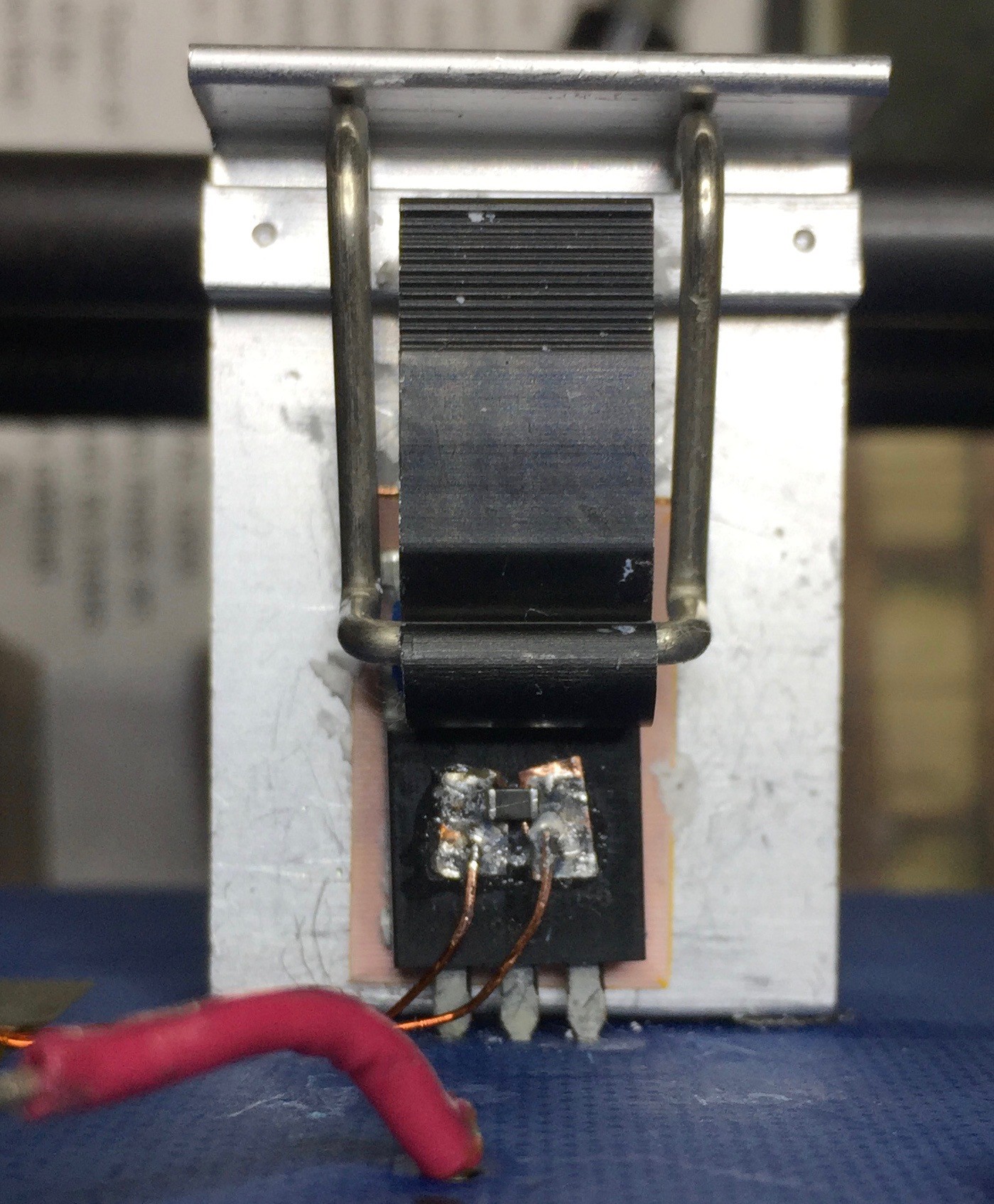
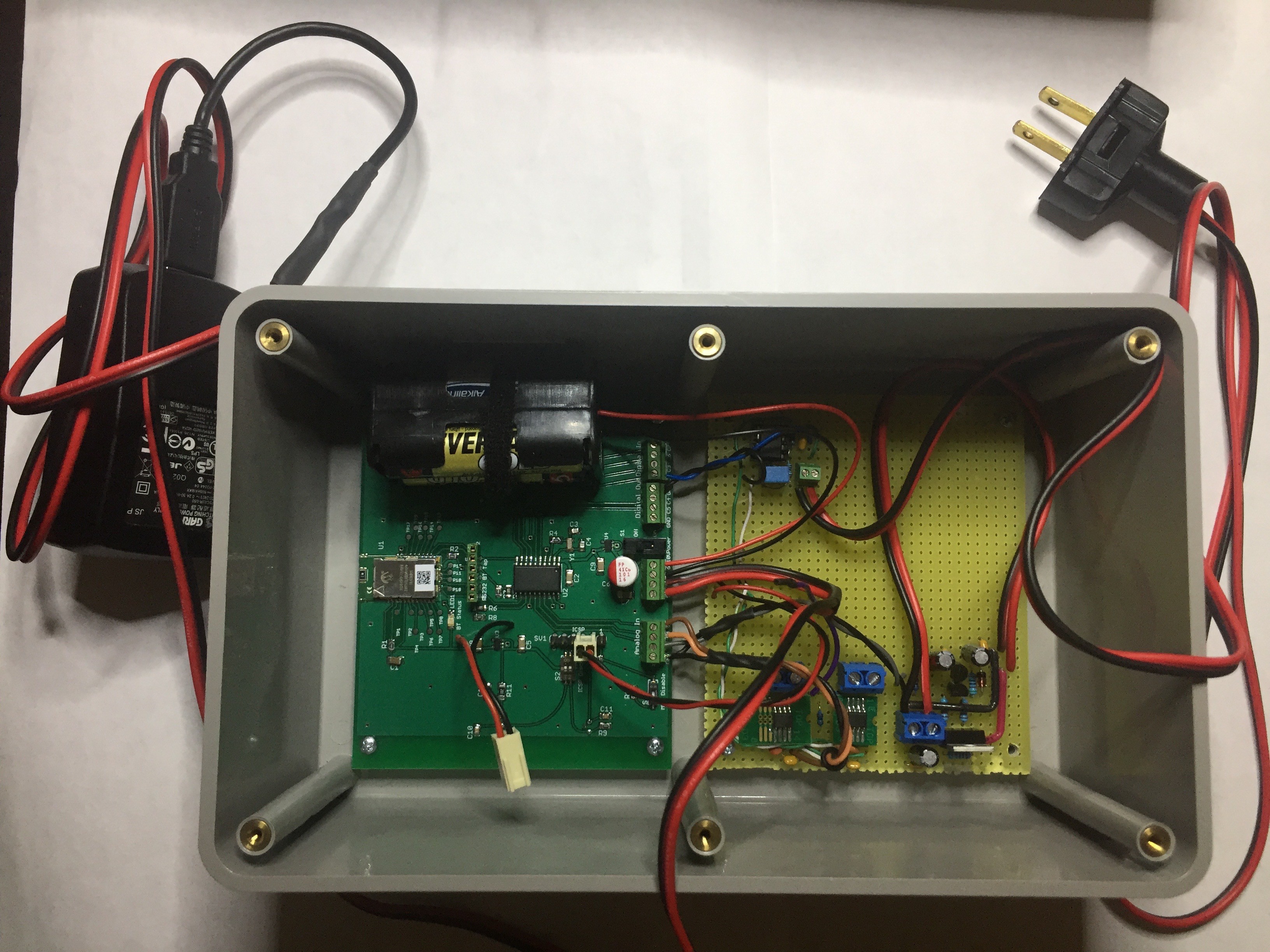
The hardware is bare-bones.  Not much more than what's necessary to support power, communications and on-board temperature & light sensors.  All remaining pins are exposed as analog or digital inputs.  Two digital pins are exposed as outputs that are optionally controlled by analog events.  They could drive a relay or other circuit to do work.

It does use a tuning fork crystal for accurate timekeeping although it hasn't been put thru temperature cycling so I can't attest to accuracy outside of room temps (I have used in 0C outdoor weather with no noticeable loss of accuracy).

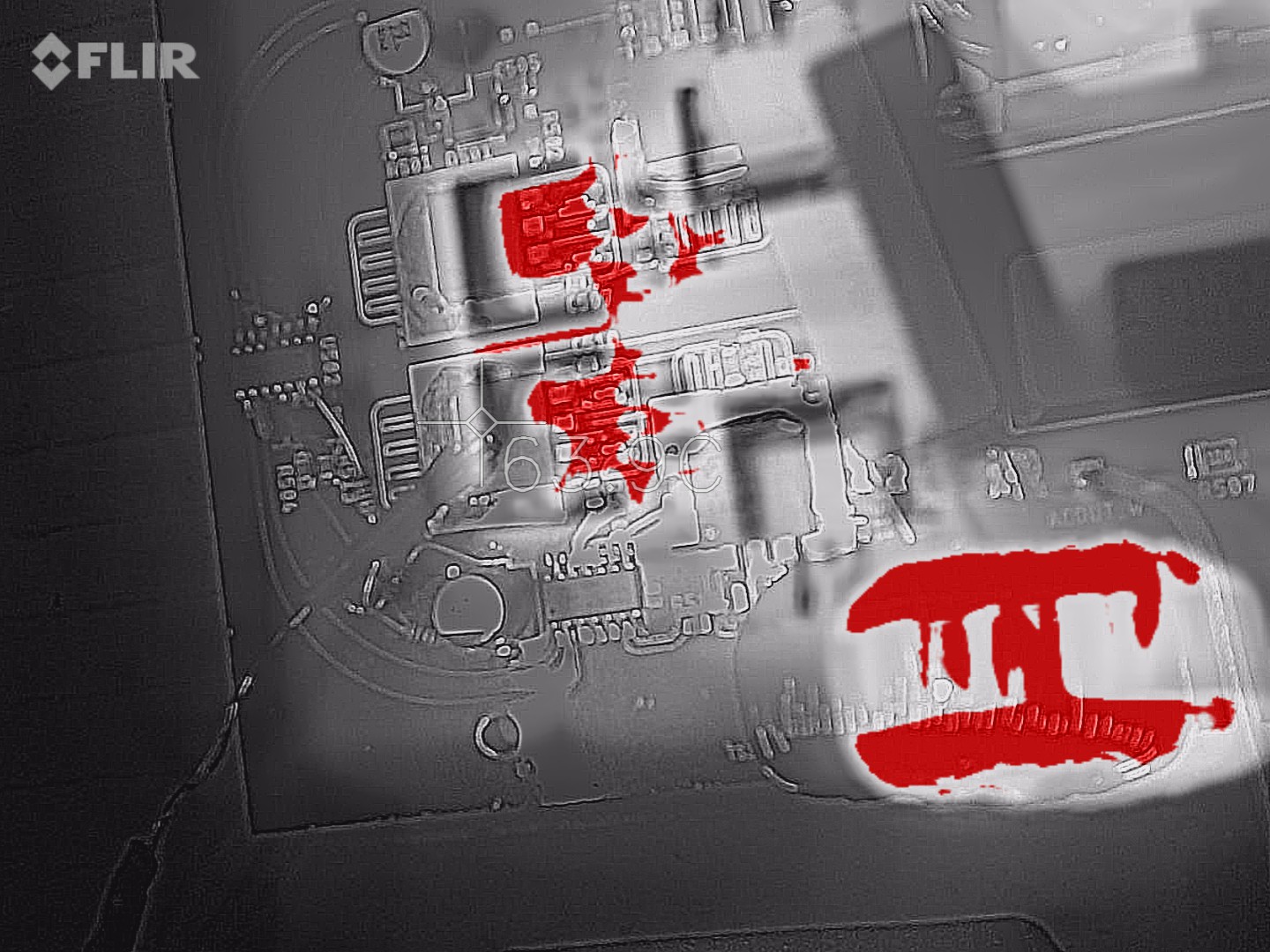
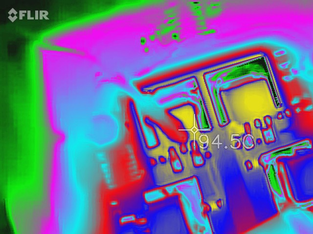
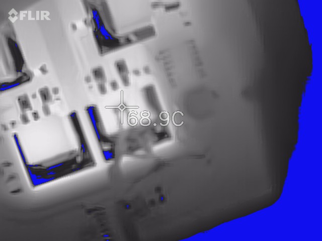
In hindsight I've found the on-board light & temp sensors to be of little value.  In typical room temperature conditions I've found that the logger's enclosure traps enough heat from the MCU & LDOs to influence the temperature by 3~4C.  With stronger temperature gradients the effect is negligible.  The light sensor is handy when the DUT responds to light but makes the logger's position crucial.  For those deciding to build this you might consider repurposing these inputs.

While intended for slow moving data - changes on the scale of 100mS or longer - I have observed it keeping up with 40 digital events / second plus two active analog channels with no data loss.

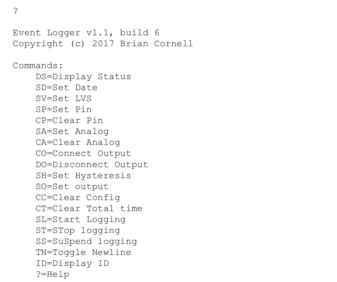
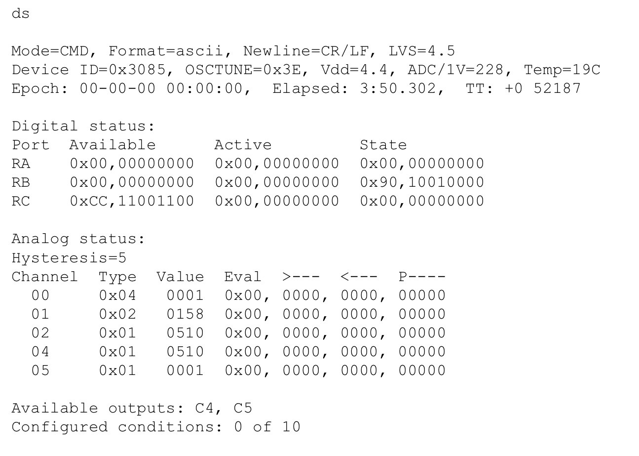
Log entries detail the hardware, software, configuration, and operation.

tlog.zip

C source code for PC-based program to display & log temperature data from data logger.

Zip Archive - 23.30 kB - 02/23/2019 at 20:53

Download

logger-sample-parser.zip

C source code for PVLOG - sample PC-based program to parse logger data stream

Zip Archive - 11.44 kB - 10/12/2018 at 15:02

Download

binary.h

Shared include file for MPLab

h - 883.00 bytes - 10/12/2018 at 14:56

Download

logger-1_0-170219-eagle.zip

Eagle schematic & PCB

Zip Archive - 110.97 kB - 10/12/2018 at 14:55

Download

logger_1-1.X-mplab.zip

MPLab project

Zip Archive - 865.60 kB - 10/12/2018 at 14:54

Download

  • Added Temperature Logging Program

    Brian Cornell02/22/2019 at 02:25 0 comments

    An on-going problem I have is getting good temperature data from the hot parts of my designs.  I have an IR camera and that is great when things are exposed on the bench but not so much when tucked away or in an enclosure.  Thermocouples are fickle and difficult to get accurate readings because of their small, bulbous shape and the resulting difficulty of securing them to a chip without damage.

    My redesign of the TS350 project is forcing me to find a solution.  It has substantial dissipation and when assembled, even on the bench, the full bridge MOSFETs won't be visible to the IR camera because of the gate driver card.

    The data logger would be an ideal platform to capture the temperature data if I could find a suitable sensor.  I experimented with the Microchip MCP9700 active sensor and Murata NTCs.  I settled on the NTCs but here's the story.

    The active sensor is attractive because it's linear and doesn't need any compensation math if your content with +/- 6C at the extremes.  The bias circuit is simple, can be driven by data logger, and comes in a SOT-23 package which is small with just enough surface area to secure to a chip.  I built one up and secured it to one of the switches on the TS350's sine bridge.  This thing emits tons of near-field EM energy and I wanted to see how it would effect readings and interfere with the Bluetooth data feed.

    Below are pictures of the probe and install.

    30AWG magnet wire attaches to the SOT-23 pads which connect to a larger shielded cable.  The case of the sensor is secured to the switch with a dab of Crazy Glue - just enough to hold it but with mild torque it can be removed without damage.

    Functionally this setup worked great but the junction-case theta made for readings far below actual case temps. 

    The sensor's temperature matched the spot reading in this IR image.

    But the case temperature was much higher.

    So I scrapped this approach and moved on to NTCs.  These are simple 2-lead devices and can obtain good measurement accuracy biased via a simple voltage-divider configuration.  They are also small and easily attached to larger chips.  Best yet, they are very cheap and could be left on the chips with just the leads removed.

    The downside is their non-linearity and accuracy over more specific ranges.  However, since the display & logging is done on a PC, math isn't a problem.  And the temperature ranges I'm concerned with are typically +40-150C which is a reasonable range to expect +/- 2C accuracy with the proper correction function.

    I built an NTC sensor, fastened to the same chip on the TS350, and retested.  Similar results to the active sensor.  The junction-case theta is the culprit.  Setup:

    NTC Temp:

    And case temp...

    To obtain accuracy, particularly at high temps, the case resistance needs to be reduced.  With either, the pads are the way to improve thermal conduction but the SOT-23 package is problematic.  However, the NTC could be soldered to copper tape which is then secured to the chip.

    For this testing I moved to a static test rig.  I used a section of 1.2mil copper tape, soldered each NTC pad to it, and then removed the center for electrical isolation.  The tape was then glued to the transistor and 28AWG magnet wire leads attached.

    It ain't pretty but it works.  Up to fourteen watts of heat was applied to the transistor and cycled up & down.  Under natural convection the NTC tracked to within -5C of the IR.  Under forced air (~400LFM) it was -7C.  In all my excitement I didn't take IR pics.

    This is acceptable for my work:  a cheap, disposable sensor with predictable performance that is unobtrusive.  In the end I fabricated a harness using 2-pin jumper sockets.  Connection is easy:  attach the probe to the transistor, attach magnet wire leads, install transistor, plug magnet wire into socket. ...

    Read more »

  • Advanced Use

    Brian Cornell10/13/2018 at 19:13 0 comments

    If you're capturing a few events over a short period of time it's easiest to capture in the emulator and manipulate the data directly or in something like Excel.  Even then I find it annoying to convert the elapsed time in the log record to chronological time. 

    So why didn't I just maintain chrono time?  Simple:  overhead.  I figured large data sets would be processed on a PC using Excel, script, or some other custom program.  That's what this log is about:  if you're logging a lot of data over a long period of time, say several days, then something better is needed.

    I've included a C program (PVLOG) I wrote to log charge / discharge data from my pilot PV system over a week or more.  It's a good example of how you can automate data collection from logger.  I'll describe the setup, operation, and considerations.

    Setup.  PVLOG is written in ANSI C and should compile & run without without modification on most U/L*ux distributions including OS X (there are pragmas to set controlling include file locations & data structures).  It has not been tested on Windows.  It can run interactively and process a file containing the binary mode output of logger or it can attach to a character device and log data real-time.

    I have a laptop setup running FreeBSD that I use for a bunch of stuff.  It has Bluetooth on it and is in range of the PV setup so that was used to run PVLOG.  Logger was paired with the BSD host and then setup as a character (terminal) device:  >rfcomm_sppd -a 99:99:99:99:99:99 -t.  You might have to change permissions on the device so PVLOG doesn't have to run with elevated permissions.

    The Call Up (CU) utility is used to start an interactive session with logger to configure the channels:

    • CH2=current from charge controller (to battery)
    • CH4=current from battery (to load)
    • CH5=battery voltage

    All three channels are set to poll on ten second intervals.  Set the output to binary and make sure LVS < Vdd.

    That's all the setup that's required.  The epoch will be set when PVLOG is run.

    Operation.  To start PVLOG for real-time capture:  >pvlog (device-path) log (output-file path & prefix).  The device-path is the full path to the character device, 'log' is the command, and output-file is where the data should be written.  PVLOG will create three files.  A log file to record termination events, a raw (r) file containing the raw data with the ADC values converted to amps/volts, and a process (p) file containing more advanced calculations and averaging.

    When PVLOG starts it connects to the logger thru the character device and expects two-way communication.  It uses the ID command to confirm logger is there and ensures it is in command mode.  It then sets the epoch and issues the start logging (SL) command.

    PVLOG will continue running until terminated by the user or when it encounters a communication or data error.  The termination cause will be written to  the log file.  If left to run for several days it will create new process & raw files for each day, starting at 00:00.

    The program writes two log files.  The raw file contains each channel record with only the ADC value converted to amps or volts.  The process file includes power calculations and averages over two time intervals:  A=1 minute and expects six samples / minute (e.g. every 10s) and B=15 minutes.  This is done for trending and to get rid of some noise.

    Considerations.  PVLOG is a good demonstration of how logging can be automated and it serves as a good template for other data logging tasks.  I thought about writing a generic engine that would also program the channel setup but I haven't had the need.

    This said, if you want to create your own logging programs beware.

    • Character devices block.  They also don't let you check for an unread byte in the stream very easily (unless you use OS-specific hooks).  This is why...
    Read more »

  • Configuration and Basic Use

    Brian Cornell10/12/2018 at 23:39 2 comments

    Configuring the logger is easy but first you need to establish communication with it.  Bluetooth SPP is used so you need a PC or computer that supports this.  Once paired with the logger you can use any terminal emulator that can access the Bluetooth device on the host.  Coolterm is available for Windows and MAC and works well.  In most U/Linux environments (include MAC) you can also use the call up (cu) command once the host creates a device for the SPP connection.  This also works well but you might need to change the newline setting (TN) once in command mode.

    Note:  it's a good idea to have Microchip's RN4677 user guide handy when first connecting.

    Once in command mode you can get help by typing a question mark (?) and pressing Enter.  You won't get detailed syntax; just the command.  This is because there's not enough program memory on the MCU for the additional constant space.  Here's the full syntax:

        DS=Display Status"
        SD=Set Date: SD YYMMDDHHMMSS (24h format)
        SV=Set low Voltage shutdown #.#
        SP=Set Pin: SP P#, P=port A/B/C, #=0-7
        CP=Clear Pin: CP P#
        SA=Set Analog:  SA C D V, C=channel, D=condition (<>P), V=value
        CA=Clear Analog:  CA C, C=channel
        CO=Connect Output:  CO P# C D, P=port, #=0-7, C=channel, D=condition (<>)
        DO=Disconnect Output:  DO P# C
        SH=Set Hysteresis:  SH #
        SO=Set output:  SO F, F=format (A)SCII or (B)inary
        CC=Clear Config (resets PIC)
        CT=Clear Total time
        SL=Start Logging
        ST=STop logging
        SS=SuSpend logging
        TN=Toggle Newline
        ID=Display ID

    This is also commented in logger.h.

    To perform logging you need to set the epoch (date & time) and configure a port or channel.  Then issue the Start Logging (SL) command.  Logger will wait five seconds before starting to give you time to setup data capture on the host side if needed.  To stop logging type ST (Stop logging) and Enter.  The command won't echo so it doesn't interfere with the data.

    By default event records are output in ASCII but you can change that to binary with  the Set Output (SO) command.

    Also be sure to check the low voltage shutdown value.  Logger will stop logging if Vdd drops below this value.

    At any point you can display the status & configuration of logger with the command DS (Display Status).  This shows operating parameters including Vdd, clock calibration, temperature, and ADC calibration along with log (event capture) settings.

    The TT field represents the Total operating Time (in minutes) of logger since last cleared.  This is stored in NVM as an unsigned 16-bit integer.  The '+0' represents the number of times the integer has rolled over.

    These are the basics.  Below are screens from a sample session showing configuration & a brief data capture.

    Help

    Status at boot - unconfigured.

    The Digital section shows the status of all ports in the MCU.  The Available column has a '1' set if that pin is available to monitor.  The screen shows four pins available to monitor:  RC7, 6, 3, and 2 (read left-right, 7-0).  The Active column shows which pins are set to monitor with a '1'.  And the State column shows the pin's status at the time the command was issued.

    The Analog section shows the available channels their type, the value read from the ADC at the time the command was issued, and the evaluation conditions.  The Type and Eval values are hex values defined in logger.h.  The greater/lesser values are decimal (as is Value) showing the ADC value to evaluate the channel to.  The 'P' or Polled column shows the seconds interval to poll the value of the channel....

    Read more »

  • Firmware

    Brian Cornell10/12/2018 at 19:59 0 comments

    Detailed operation of the firmware is best obtained by studying the code.  This log describes general operation.  The firmware can be divided into four sections:

    1. Command
    2. Communications
    3. Logging
    4. Timing

    The Command section handles operator input.  Logger is configured thru the Bluetooth SPP interface.  All commands are 1~2 characters in length and contain a variable number of parameters depending on their function.  Data is parsed, bounds checked and stored as binary data in control structures.

    All Communications is handled by an RS232 module.  Data received generates an interrupt which is processed by a function called from the ISR.  Received data is stored in a buffer which is terminated when a carriage return (CR) is received.  Receive operations occur in the background via ISR; the foreground process can poll for status of received data, clear the buffer, and process once a CR is received.

    Data transmission is done by the foreground process.  In command mode responses to commands are printed using the standard C library printf function.  This calls putch in the RS232 module to send the formatted output.  In logging mode data transmission is performed by the TxLog function.  TxLog is called on each pass thru the logging loop.

    CTS/RTS flow control is used between the MCU and Bluetooth module to prevent data loss.

    The Logging code can be further broken down into three areas:  analog, digital, and buffer management.

    Analog logging is done by polling.  When logging is started, the foreground control loop calls the PollAnalog function.  It's responsible for determining what channels are active, the evaluation condition(s), measurement, data capture, and evaluating / executing output conditions.

    Since the MCU has only one ADC, each channel that's monitored is done so in a four-step process:

    1. Select the channel
    2. Acquire (e.g. charge S&H cap)
    3. Convert
    4. Evaluate

    It takes four calls of the PollAnalog function to get thru each active channel.  This limits the maximum sample rate but makes for much more efficient code which is necessary on this memory constrained MCU.

    Linear hysteresis is employed for analog evaluations.  The user can specify how many successive samples must meet criteria before an event is logged.  Since it is operating in a polled environment to say that it is linear is not entirely true; the timing will vary based on logging activity which changes the time constant of the filter.

    Digital logging is interrupt driven and uses the IOC (Interrupt On Change) feature.  When logging is enabled for a digital pin a change in its logic state triggers an interrupt.  An event record is created and written to the logging buffer.  To minimize the overhead in the ISR the hysteresis feature isn't available on digital pins; this means that external debounce / signal conditioning is necessary.

    Buffer management is about getting event data out of logger.  Both analog & digital events call wrBuffer to create an event record.  The data varies based on type, but all events contain record type, sequence number, and elapsed time.  Reference logger.h for all the details.  Records are written to a circular buffer.  If full a status record is added (space is reserved for it) to note and subsequent event data is discarded until space is free.

    During logging the foreground process calls TxLog on every pass to process buffer data.  Once a complete record is transmitted the buffer count is decremented & pointers are updated.

    System Timing is performed in the ISR and controlled by two timers.  Timer1 is driven by an external [tuning fork] crystal and provides a precise interrupt every second.  Timer2 is driven by the MCU's internal oscillator at a frequency of 1kHz which allows 1mS timing.  The combination of timer 1 & 2 allow the timing of events down to the millisecond.  Timer1 also provides service for the user-available...

    Read more »

  • Hardware

    Brian Cornell10/12/2018 at 18:35 0 comments

    The hardware design is simple.  Most of the PIC’s pins are dedicated to data collection.  The PIC's Vdd=5V so, the RS232 output lines require voltage dividers to interface to the Bluetooth module.  A higher Vdd was done to provide the PIC’s ADC a more range at the expense of resolution (4.88 vs. 3.22 mV per bit).  A tuning fork crystal is connected to the secondary oscillator to keep accurate time for logging.

    Microchip’s RN4677 hybrid BT Classic / BLE module is used for its support of SPP, command line interface, and ease of use.  Most of its features aren’t used; it essentially provides a wireless connection for the serial data.  You should be able to use it out of the box:  default settings are 115.2kbps, 8 data bits, 1 stop, no parity.  I do recommend changing the service name.  I do recommend changing the service name for easier identification.

    Power is supplied by batteries or an external power supply to LDO regulators.  The unit will accept 6-10VDC or the 5V LDO can be bypassed by connecting regulated 5VDC to the appropriate terminal lug.  When this is done the batteries can serve as a UPS should external power be lost.

    As previously mentioned, I opted to include on-board light & temperature sensors since these are often needed in the testing I do.  It also gives the unit some versatility to perform basic environment monitoring & control.  These sensors share pins with ICSP so DIP switches are used to disconnect when the PIC’s firmware needs updating.

    Three additional analog inputs are made available on a terminal block as are four digital inputs and two digital outputs.  A 6-pin ICSP header is included for firmware updates.  Also included are provisions for connecting to the RS232 bus in case the RN4677 requires changes.  The MPU Disable switch holds the PIC in reset so it doesn’t interfere with communication.

    Note that the RN4677 might not be available and I believe Microchip recommends the RN4678 which should be pin-compatible.

    The hardware footprint could be compressed but I opted for this because of extensibility:  real-world connects require additional interface circuitry.  I had a case in mind that would allow for the stacking of interface cards.

    Here's a picture of a setup I've used for a couple of different projects.

    The adapter to the left of the enclosure is a 5V USB supply for applications where AC is handy.  Otherwise 4 AA batteries supply a nominal 6V to the LDO..

    The perf board contains a number of discrete circuits.  The top left is a comparator that drives one of logger's digital inputs.  It is connected to the AC cord on the right side of the box.  The plug contains a neon lamp fused to photo-transistor and is used to indicate when an AC circuit is energized without introducing an impedance to the line when off.  The bottom right is an LDO that allows logger to be powered by DC sources higher than 10V.  The bottom left contains a set of hall effect current sensors and a voltage divider for sensing DC voltages between 10~20V.  All of these employ noise filtering and connect to analog inputs.  The jumper from the ICSP pins delivers 5V to the interface circuitry.

View all 5 project logs

Enjoy this project?

Share

Discussions

Similar Projects

Does this project spark your interest?

Become a member to follow this project and never miss any updates