Configuring the logger is easy but first you need to establish communication with it. Bluetooth SPP is used so you need a PC or computer that supports this. Once paired with the logger you can use any terminal emulator that can access the Bluetooth device on the host. Coolterm is available for Windows and MAC and works well. In most U/Linux environments (include MAC) you can also use the call up (cu) command once the host creates a device for the SPP connection. This also works well but you might need to change the newline setting (TN) once in command mode.
Note: it's a good idea to have Microchip's RN4677 user guide handy when first connecting.
Once in command mode you can get help by typing a question mark (?) and pressing Enter. You won't get detailed syntax; just the command. This is because there's not enough program memory on the MCU for the additional constant space. Here's the full syntax:
DS=Display Status"
SD=Set Date: SD YYMMDDHHMMSS (24h format)
SV=Set low Voltage shutdown #.#
SP=Set Pin: SP P#, P=port A/B/C, #=0-7
CP=Clear Pin: CP P#
SA=Set Analog: SA C D V, C=channel, D=condition (<>P), V=value
CA=Clear Analog: CA C, C=channel
CO=Connect Output: CO P# C D, P=port, #=0-7, C=channel, D=condition (<>)
DO=Disconnect Output: DO P# C
SH=Set Hysteresis: SH #
SO=Set output: SO F, F=format (A)SCII or (B)inary
CC=Clear Config (resets PIC)
CT=Clear Total time
SL=Start Logging
ST=STop logging
SS=SuSpend logging
TN=Toggle Newline
ID=Display ID
This is also commented in logger.h.
To perform logging you need to set the epoch (date & time) and configure a port or channel. Then issue the Start Logging (SL) command. Logger will wait five seconds before starting to give you time to setup data capture on the host side if needed. To stop logging type ST (Stop logging) and Enter. The command won't echo so it doesn't interfere with the data.
By default event records are output in ASCII but you can change that to binary with the Set Output (SO) command.
Also be sure to check the low voltage shutdown value. Logger will stop logging if Vdd drops below this value.
At any point you can display the status & configuration of logger with the command DS (Display Status). This shows operating parameters including Vdd, clock calibration, temperature, and ADC calibration along with log (event capture) settings.
The TT field represents the Total operating Time (in minutes) of logger since last cleared. This is stored in NVM as an unsigned 16-bit integer. The '+0' represents the number of times the integer has rolled over.
These are the basics. Below are screens from a sample session showing configuration & a brief data capture.
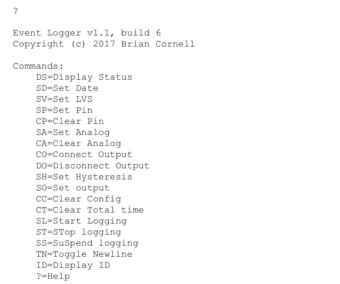
Help
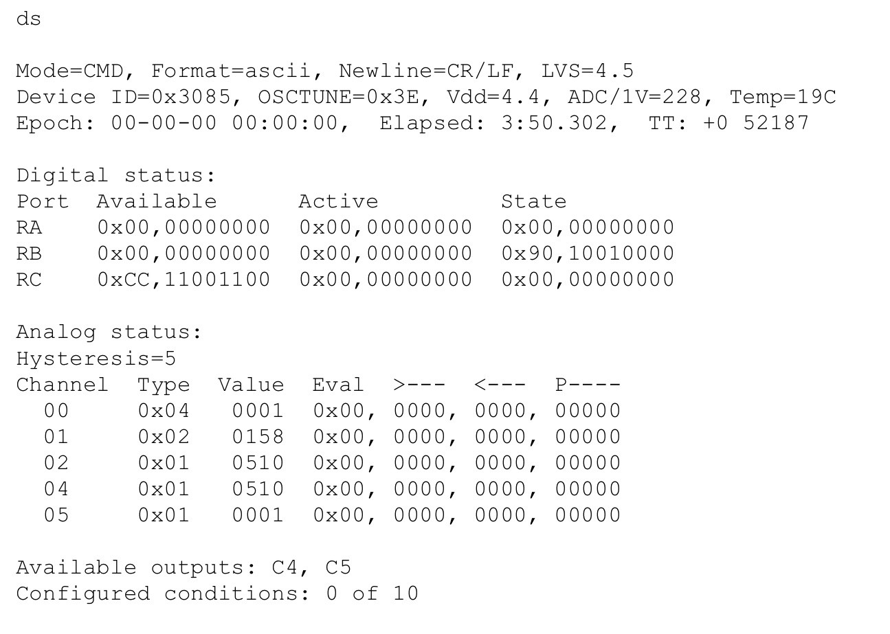
Status at boot - unconfigured.
The Digital section shows the status of all ports in the MCU. The Available column has a '1' set if that pin is available to monitor. The screen shows four pins available to monitor: RC7, 6, 3, and 2 (read left-right, 7-0). The Active column shows which pins are set to monitor with a '1'. And the State column shows the pin's status at the time the command was issued.
The Analog section shows the available channels their type, the value read from the ADC at the time the command was issued, and the evaluation conditions. The Type and Eval values are hex values defined in logger.h. The greater/lesser values are decimal (as is Value) showing the ADC value to evaluate the channel to. The 'P' or Polled column shows the seconds interval to poll the value of the channel.
Conditional outputs would be listed after the 'Configured conditions' heading.
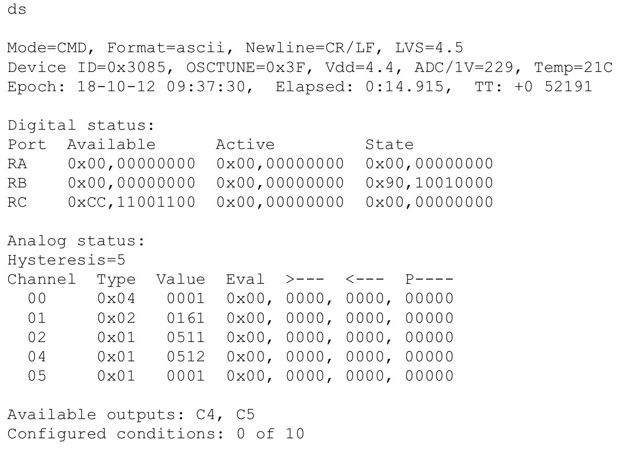
Status with epoch set.
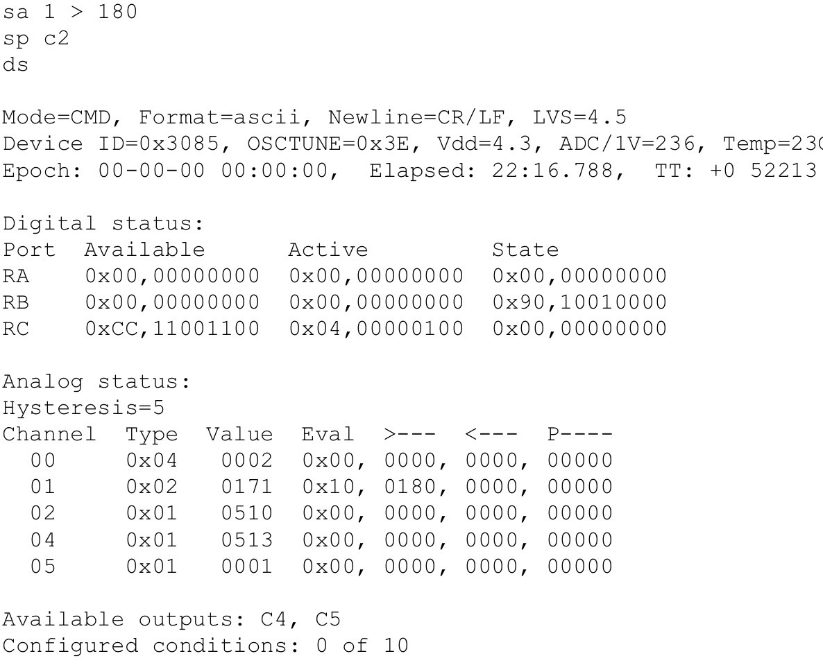
Configuring analog channel 1 and digital pin C2. Note C2 bit in Active column set to '1' and analog channel 1 '>' value set to 180.
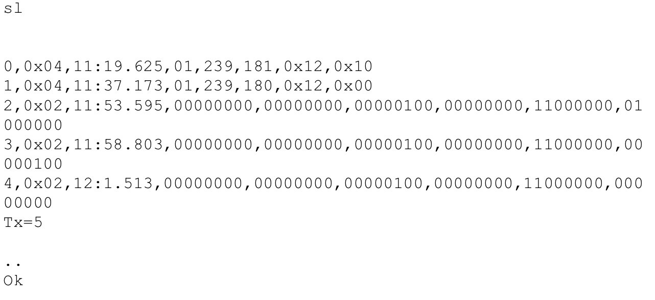
ASCII logging output using configuration from above.
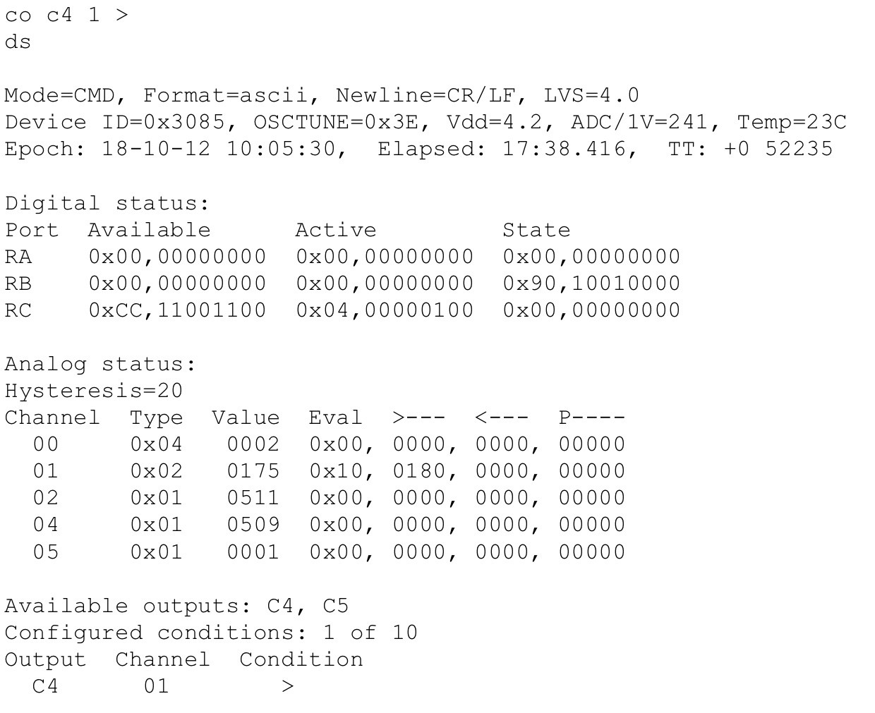
Adding a conditional output to configured analog event on channel one. When it evaluates TRUE output C4 will be set TRUE.
Discussions
Become a Hackaday.io Member
Create an account to leave a comment. Already have an account? Log In.
Hi Jan, yes that would be great. I thought about a better interface and also SPI or I2C NVM so I didn't have to rely on the BT connection. If I do more development I'll use a 16 or 32 bit MCU.
Are you sure? yes | no
Super interesting logs, especially regarding software on the PC side... Haven't done any of that but I'd like a small one exe GUI some day where I can change settings and log data of my loggers. I guess I will dive deeper into python and just try it in command line first...
Are you sure? yes | no