 Beaglebreath
A couple days ago, I took a dual channel Oscilloscope and hooked up Channel 1 to the Laser's REF output signal. That gave me a picture of a square-waveish signal that was about 2.1 MHz. I then hooked up Channel 2 to the MEAS signal on the Optical Receiver. This too, was producing a 2.1 MHz signal.
I setup the movable Retroreflector, so that it would wiggle a few 10's of millions of an inch on it's mounting screws. (This was because I had not setup the alignment of the Retroreflector at it's remote location). As I moved the Retroreflector back and forth, I could watch a corresponding apparent phase shift between the two signals. The relative change in phase, in terms of direction and speed, corresponded with my moving the Retroreflector by hand.
My suspicion is, that each 360° phase shift cooresponds to a 25 µinch movement of the Retroreflector. The apparent phase shift is due to the shrinking and stretching of the MEAS signal due to a Doppler shift when the Retroreflector moves. For each 360° phase change, one whole count is changed on the accumulated MEAS counts as compared to the REF counts. When there is no relative motion, the REF and MEAS return to the same frequency, and there is no additional change in the relative frequency counts.
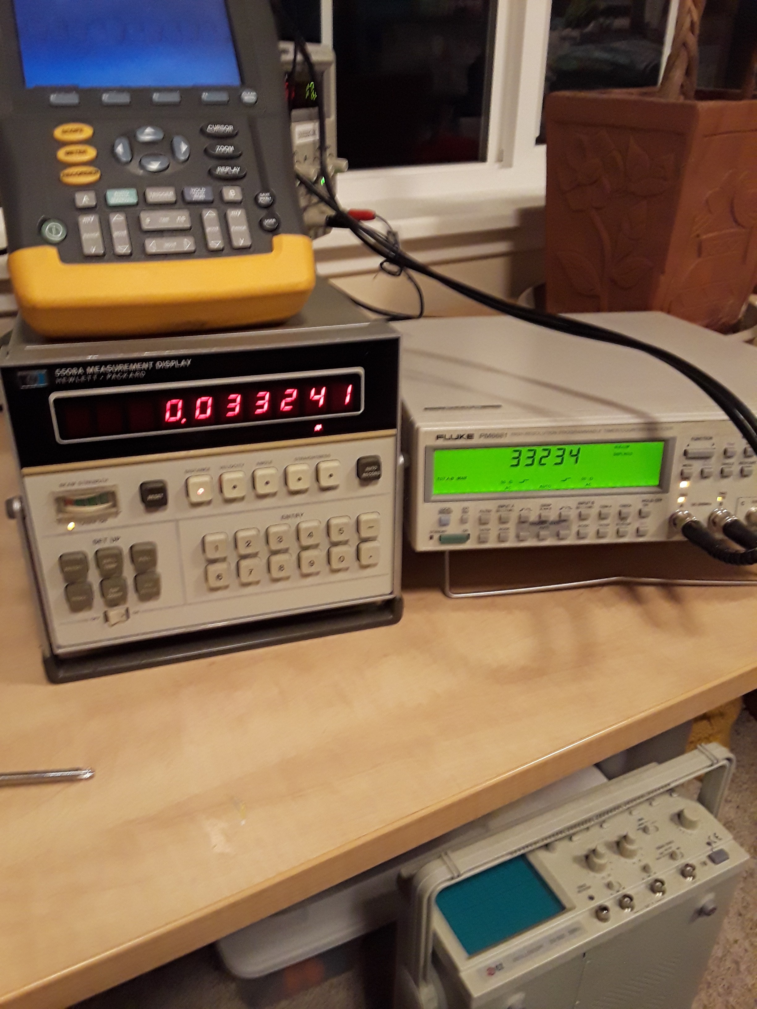
After playing with the scope, I tried hooking the REF and MEAS to a Fluke PM6681 Dual channel Frequency Counter/Analyzer. After setting up the input loading and thresholds I got a reliable count of the waves from each channel.
The Frequency Counter has many modes to choose from to help analyze the signals. I put the Frequency Counter into it's A-B Counter Mode. In this mode, the Frequency Counter counts the waves that trigger the counter and displays the difference of the two counts on it's front display.
At that point I had a number that would change as the number on the output of the Interferometer Display changed. Both values would increase and decrease in time with regard to each other.
Next I activated the MATH functions of the PM6681. I applied a linear equation to the A-B output. This allowed me to scale the output to match the Interferometer display. The MATH function also allows an easy way to reset to Counters to 0.
That was fun :) I got the scale factor close enough to have a mostly precise agreement between the two instruments.
Next I began trying to think of a scheme to make a Raspberry Pi or a micrcontroller to the work that the instruments are doing. I decided that I did not want a Raspberry Pi spending it's life watching the inputs and counting waves. It had more important things to do...
I spent several days batting around in the wilderness, reading scholarly documents about phase-detection, and other things when I came across a video by Ben Krasnow on Youtube, (His Video). His video was about a fiber optic joystick, but he was using a decoder chip which caught my attention. And that lead me to discover the Avago HCTL-2017 .
This is a CMOS IC, which has a quadrature decoder, up/down counter, and 8/16-bit output modes. This guy can clock up to 33 MHz too. I then ordered a few and had them in hand last week. Spent some quality time with the breadboard, and got the HCTL-2017 wired up to the Raspberry Pi. I wrote some Python scripts to control the GPIO, that was being used to control and read from the IC.
By Friday night, I had a short Python Script controlling the HCTL-2017. I was reading noise from the inputs, since I was too scared to connect the interferometer to the breadboard.
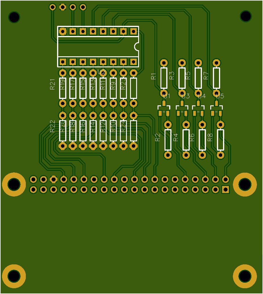
I began designing a printed circuit board to replace the breadboard circuit. This is what I ended up with. It was ordered on Saturday. I'm now waiting with baited breath for it to arrive.
Discussions
Become a Hackaday.io Member
Create an account to leave a comment. Already have an account? Log In.