 Jeff Wahaus
The DC boost module used for stepping up the battery's output voltage is rated at 2A and can boost the output voltage as high as 28V if desired. The boost module has a potentiometer for adjusting the output voltage. When using the LCD connector the output voltage should be kept between 4.5V and 7.0V since the LCD is directly powered from the boost module's generated output voltage.
Some practical guidance when using this circuit: Although the boost module in this circuit is rated at 2A it is likely not a good idea to draw this much current continuously when using this module as it will get very hot as you approach the module's upper limits. Keep in mind when calculating current draw that the battery's current draw will be higher than the output current. For example if the output is using 5V at 1 amp (5 watts of power) then the boost module (assuming 90% efficiency) is using 1.5 amps at 3.7 volts.
Update: I've done some testing on just how much current this power bank can supply at 5V. I also monitored the temperature of the voltage boost converter to see if it gets too hot during high current draw.

The upper usable limit this circuit can produce is about 1.2 Amps at 5.1 Volts. That's just enough to power the Raspberry Pi 3 with 7" TFT display, camera, and wireless keyboard to which it's attached for around 2 hours. The temperature of the boost module got up to around 70C which is pretty hot to the touch but within the acceptable temperature range.
To find the absolute maximum current this circuit can supply I attached a 3.3 Ohm resistor to the current monitor's leads and it briefly hit 1.48 Amps @ 4.9V before the current monitor's display cut out due to low voltage. This resistor will draw 1.5 Amps at 5 Volts.


 Anuradha Gunawardhana
 icstation
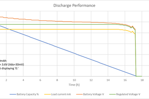
 George
 Stefan Wagner
Hi there i have been working on project that involves measuring voltage divider using attiny85.
while measuring the voltage level of the voltage divider circuit the voltage value deviates from actual theoretical value and i am not able to understand why is it happening can u help me understand the problem!