 Colin McAllister
This week I was able to finish the two board designs for the initial prototype. As I said in the previous log, I want to design a daughter board that is able to create a serial interface between the soil probe and a computer. This will allow the soil probe to initially charge the battery and also be programmed.
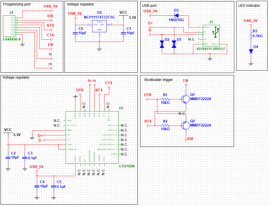
Programmer Board
The daughter programming board was pretty simple to build. The design incorporates a similar design to the USB to Serial circuit used on the ESP32 DevKitC and Adafruit HUZZAH32. I really like the design's ability to auto program the ESP32 by toggling the EN and IO0 pins. I wanted to use this feature to avoid having to place reset & bootloader buttons on the soil probe. The programmer is powered by the 5 volts supplied by the USB port and regulated with a fixed 3.3v linear regulator. The USB bus is also protected with a schottky diode and ESD protection devices. I also added a small surface mount LED to indicate when the device is powered on.
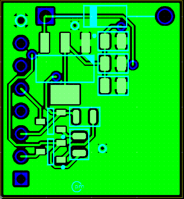
Laying out the components was not too difficult either. I did challenge myself to try and place components on both sides of the board and felt like I saved a little bit of space in the process. The programmer and probe will be connected with a standard 8-pin header. For the final design I hope to only have exposed pads which will rest on a bed of nails.

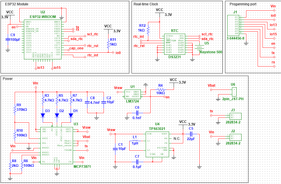
Soil probe
The soil probe was a much more complicated design compared to the programmer board. The number of components was much larger, and featured an odd component that was hard to make a footprint for in Ultiboard.
The most difficult part of the design was the circuitry that will manage the battery and power the ESP32. I was inspired by Adafruit's battery management board. I decided to also use the MCP73871 lithium battery charger. Since this device will be on its own, I figured it would be best to actually use a thermistor to monitor the battery's temperature. To simplify the circuitry, I added no protection for the solar panel if the device is powered by USB, but figured this was not necessary anyways because the solar panel will be added after programming.
Based off my understanding the output for the load from the MCP73871 is not regulated, so I decided to use a buck-boost regulator to ensure the output for the ESP32 is regulated to 3.3 volts. I used Texas Instruments' WEBENCH tool to get a design for the buck-boost circuit. The last element of the power circuit is the LM3724, which is a microprocessor reset circuit. This component watches the battery's voltage and will ensure that the ESP32 does not power on if the voltage drops below 2.5 volts.
The last important part of the circuit is the DS3231 real-time clock, which will preserve the current time and also wake the ESP32 at certain time intervals. This will allow a network of probes to power on at the same exact time to create the mesh network that the sensor data will be transmitted over.
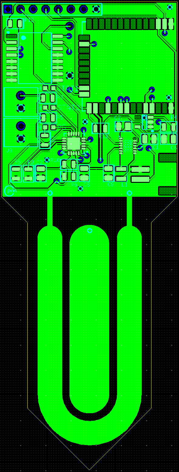
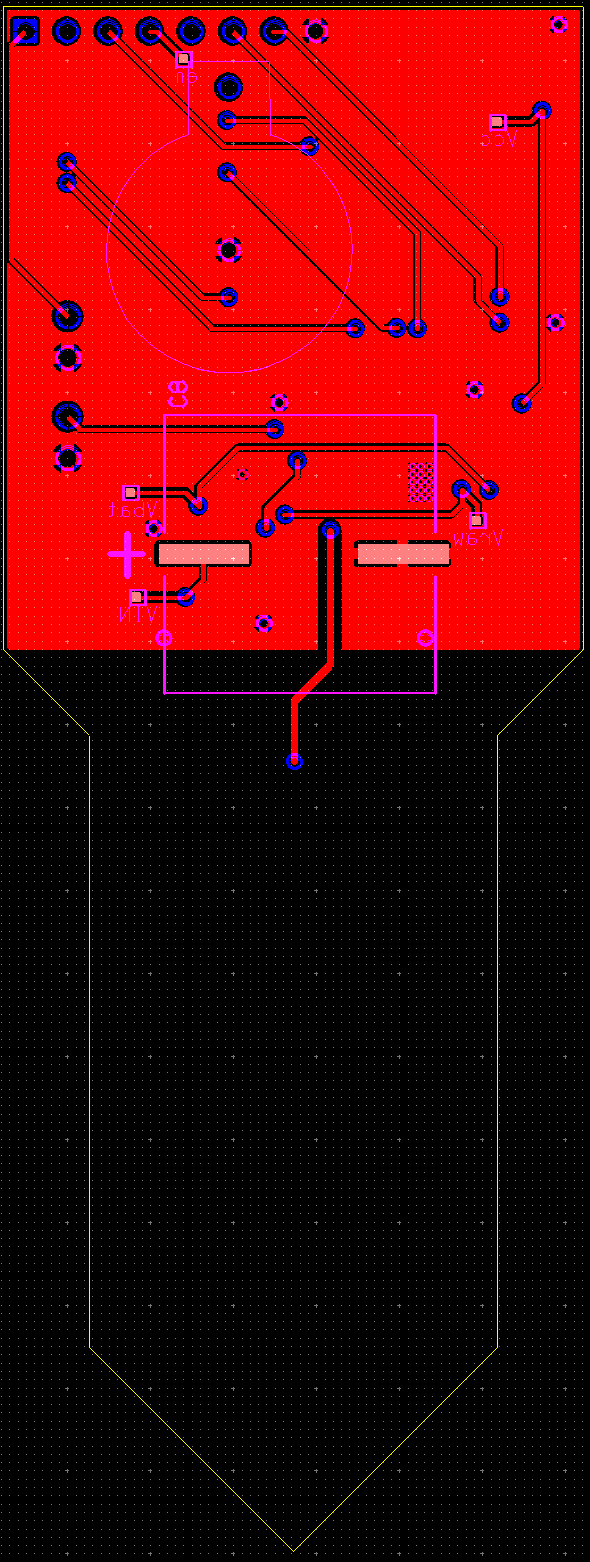
Laying out the above circuit was definitely challenging. I tried my best to minimize the size of the board and am happy with the final size. Components were mostly placed on the front of the board, with the exception being the backup battery for the real time clock. I would like the final board to have an empty back so the lithium battery can be affixed to the back. I included two images of the board to show the traces along with an image of the planes. The image with the planes clearly shows the capacitive probe that will measure the soil moisture.
I also added some test points to ensure that the SMPS and battery charger are working correctly.
Once the boards are ordered I will upload the gerber files. If you would like to see the Multisim or Ultiboard files please contact me.
Discussions
Become a Hackaday.io Member
Create an account to leave a comment. Already have an account? Log In.