 Mike Teachman
It turns out that the Adafruit I2S MEMS Microphone breakout board does not work properly with ESP32 microcontrollers. The Adafruit breakout board uses the SPH0645LM4H MEMS microphone.
What's going on? I have discovered a timing incompatibility between the ESP32 and the I2S microphone - the ESP32 samples data on the rising edge of the I2S clock, exactly the same time as the sample data is changing from the SPH0645LM4H microphone. The unfortunate end result is that every 18-bit sample from the microphone is shifted one bit to the left - the MSB is lost and a '0' appears as the LSB.... not good.
A couple of years ago this issue was discussed on an Adafruit forum...but no real answer came out of it.
Let's take a deeper dive to see what is happening.
The ESP32 Technical Reference Manual describes the expected timing between WS, BCK, and SD
"WS and SD signals in the I2S module change on the falling edge of BCK, while the SD signal can be sampled on the rising edge of BCK"
The key part is "sampled on the rising edge of BCK".
A timing diagram in the ESP32 Technical Reference Manual shows the expected timing for an I2S slave device. Shown below:

The SPH0645LM4H device implements the timing diagram shown below. Notice that DATA (SD) transitions on the rising edge of CLK.
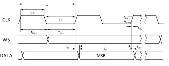
The SPH0645LM4H datasheet specificies a Max Tdc = 65.92ns, but surprisingly no Min value for Tdc.
This doesn't look like a good situation - data changing when it is being sampled is not a recommended design practice !
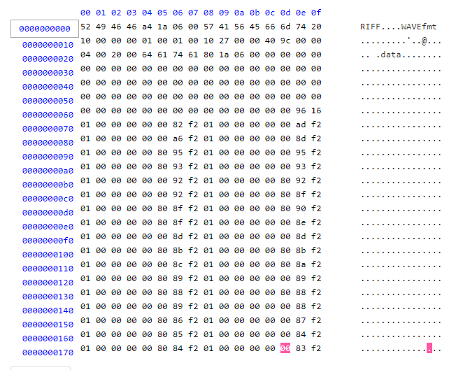
The captured sample data clearly shows a problem -- the data shows that the ESP32 uses the MSB of the Left channel as the LSB of the Right channel. That line I just wrote is likely confusing! Let's look at an example to get clarity.
The WAV file data shown below was captured using the ESP32 I2S interface. The "0x01" value bytes that appear in two columns are the least significant bytes for the Right channel. They should be 0x00 as the microphone is configured to only output sample data on the left channel (WS=low). But they are 0x01 because the MSB of the Left channel is clocked in as the LSB of the Right channel by the ESP32. A sharp eye will notice that every Left channel sample has the LSB equal to zero (e.g. always 0x80 and 0x00...never 0xC0 or 0x40) - that happens when the "19th" bit (which is pulled down to zero when the data bus goes tri-state) is sampled as the LSB "18th" bit. Note that the data is in little endian format.
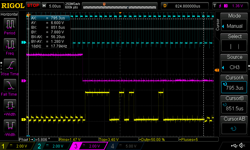
I was able to use an oscilloscope to capture the I2S data bit stream that is associated with the above WAV file. The scope capture below shows BCK, WS, and SD (top to bottom) of the 2nd non-zero audio sample. The bit stream on the SD signal shows a sample value of 0xF9 0x41 0x00 0x00. Now, compare to the 2nd Left channel sample in the WAV file above (in line starting with 0x70) which has a value = 0xF2 0x82 0x00 0x00 (converted from little endian)
if you take sample = 0xF9 0x41 0x00 0x00 (the "correct" value seen in the bit stream) and shift it L by one bit you get sample = 0xF2 0x82 0x00 0x00 (the "wrong" value sampled by the ESP32) which is seen in the WAV file data.
This shows the compatibility problem between the ESP32 I2S interface and the SPH0645LM4H microphone.
I was hoping for a workaround. But, I could not find a means to adapt the timing of either the microphone or the ESP32 to make them compatible. There is a (complex) firmware solution where the undesired bit shift can be undone. I did not pursue that approach.
A simple solution involved changing to a different I2S microphone breakout board using timing that aligns with the ESP32 - the INMP441 I2S MEMS microphone seems like a good match. The datasheet shows that the INMP441 device has I2S timing expected by the ESP32.
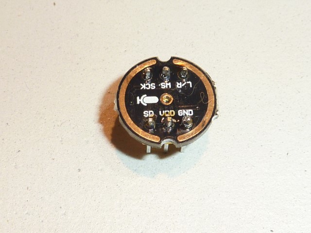
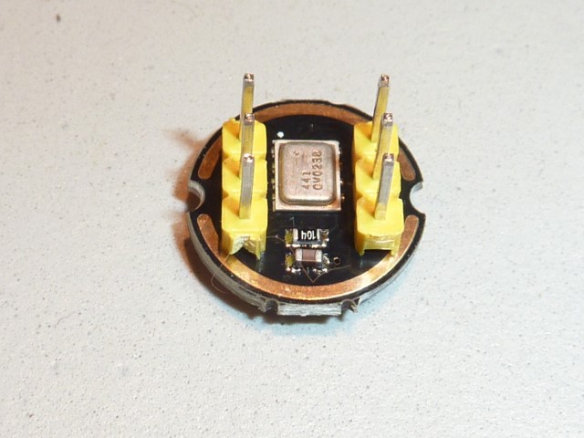
I found an Asian supplier that offers this I2S microphone in a breakout board. Here are photos.
An oscilloscope capture shows that this microphone will work with the ESP32 I2S interface. Notice that SD (purple) changes on the falling edge of BCK (yellow). The ESP32 samples on the rising edge of BCK, in the middle of each sample bit.
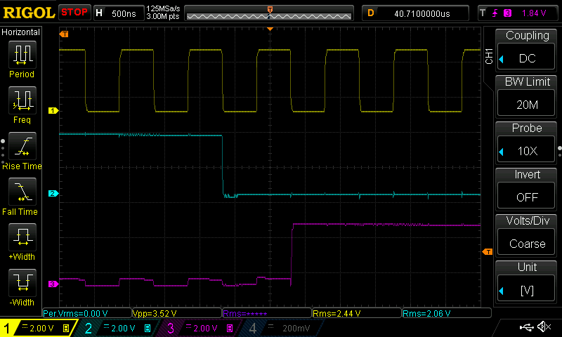
End result: The audio sample data captured by the ESP32 using this new I2S microphone is correct.
Discussions
Become a Hackaday.io Member
Create an account to leave a comment. Already have an account? Log In.
Hi, it works fine here without any issues on an esp32:
The following returns data of:
sampleRate: 16000
sampleSize: 16
channels: 1
singed: true
Setup :
const i2s_config_t i2s_config = {
.mode = i2s_mode_t(I2S_MODE_MASTER | I2S_MODE_RX), // Receive, not transfer
.sample_rate = 16000, // 16KHz
.bits_per_sample = I2S_BITS_PER_SAMPLE_32BIT, // could only get it to work with 32bits
.channel_format = I2S_CHANNEL_FMT_ONLY_RIGHT, // although the SEL config should be left, it seems to transmit on right
.communication_format = i2s_comm_format_t(I2S_COMM_FORMAT_I2S | I2S_COMM_FORMAT_I2S_MSB),
.intr_alloc_flags = ESP_INTR_FLAG_LEVEL1, // Interrupt level 1
.dma_buf_count = 8, // number of buffers
.dma_buf_len = BLOCK_SIZE // samples per buffer
};
// The pin config as per the setup
const i2s_pin_config_t pin_config = {
.bck_io_num = 4, // BCKL
.ws_io_num = 15, // LRCL
.data_out_num = -1, // not used (only for speakers)
.data_in_num = 14 // DOUT
};
// Configuring the I2S driver and pins.
// This function must be called before any I2S driver read/write operations.
esp_err_t err = i2s_driver_install(I2S_PORT, &i2s_config, 0, NULL);
if (err != ESP_OK)
{
Serial.printf("Failed installing driver: %d\n", err);
while (true)
;
}
err = i2s_set_pin(I2S_PORT, &pin_config);
if (err != ESP_OK)
{
Serial.printf("Failed setting pin: %d\n", err);
while (true)
;
}
Serial.println("I2S driver installed.");
Reading: (converts to 16 bit
{
size_t bytes_read;
int32_t *rsp_in = (int32_t *)malloc(AEC_FRAME_BYTES * I2S_CHANNEL_DEVICES);
while (1)
{
i2s_read(I2S_PORT, rsp_in, AEC_FRAME_BYTES * I2S_CHANNEL_DEVICES, &bytes_read, portMAX_DELAY);
int cnt = 0;
//int32_, thus 4 bytes
for (int i = 0; i < bytes_read / 4; i++)
{
int32_t sample = rsp_in[i];
sample >>= 14;
int16_t out = sample;
//int16_t out = (int16_t) (~(sample >> 14) + 1);
//CONVERTED TO SIGNED 16 BIT SAMPLE, save in same array
((int16_t *)rsp_in)[i] = out;
cnt++;
}
bytes_read = bytes_read / 2; //reduce array size, since int16_t now
publishAudioData((uint8_t *)rsp_in, bytes_read);
}
}
Are you sure? yes | no
the workaround regarding the SPH0645LM4H. set the delay for the SD signal to 2 cycles using the I2S_TIMING_REG register after setting up the i2s pin configuration
REG_SET_BIT( I2S_TIMING_REG(I2S_NUM),BIT(9)); /* #include "soc/i2s_reg.h" I2S_NUM -> 0 or 1*/
Also make sure the Philips mode is active
REG_SET_BIT( I2S_CONF_REG(I2S_NUM), I2S_RX_MSB_SHIFT);
The i2s_driver_install(...) function seems like not to implement this correctly.
This will read the MSB a bit "later" at the correct time.
Are you sure? yes | no
Hi Manuel, I'm also trying to get SPH0645 to work with ESP32 but I'm not really a firmware engineer, so I don't quite understand your workaround. Do you happen to have a working sample sketch that I could refer to? I'd really appreciate that!
Are you sure? yes | no