 Mike Teachman
Two new components were added to the breadboard prototype
- DS3231 clock module
- SSD1306 OLED display
DS3231 real time clock module
The Street Sense unit will have an onboard logging feature, where sensor data will be recorded to SD Card, every 15 minutes. Done professionally, timestamped sample data is recorded on the 15 minute mark, 00, 15, 30, and 45 mins (rather than randomly starting at some minute value). This requirement necessitates some sort of accurate clock source.
The DS3231 clock module is an ideal device for this purpose -- it includes a constantly running on-board clock that is maintained by a single coin battery. This means the clock keeps running even when the unit is not powered. This particular clock module was chosen for its extremely low drift specification of +- 2ppm. Over one year the clock will drift by a maximum of ~1 minute.
The clock module also has 2 built-in alarms. You can set an alarm date/time. When the clock reaches the alarm time an on-board register flags the alarm. The MicroPython code can detect this alarm. The alarm feature will be used to time the 15 minute recording intervals discussed above.
The communication interface is I2C -- my favorite. The LoBo version of MicroPython that I'm using has excellent I2C support.
A google hunt for "DS3231 MicroPython" revealed a few open source libraries. I chose a library with alarm support and by an author know in the community for excellence in driver design (Radomir Dopieralski).
https://github.com/adafruit/Adafruit-uRTC
https://micropython-urtc.readthedocs.io/en/latest/
There is one small bug in the alarm implementation. It was an easy one-line fix. I submitted a pull request for the fix.
https://github.com/adafruit/Adafruit-uRTC/pull/9
The current consumption was measured at 1.2 mA. The module has a single LED which likely accounts for most of the current. I'll likely remove the LED as it adds little value.
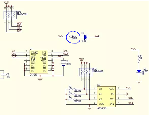
One other important note about this module. It is recommended to remove resistor R5 to disable the recharging circuit. The coin cell being used is not rechargeable. R5 is circled in the schematic below. I removed it by heating the surface mount resistor with a soldering iron.
SSD1306 OLED display
A display will be useful when commissioning the unit to see that the sensors are working prior to installation. As well, there might be a need to select different operating modes during on-site commissioning. The SSD1306 is a compact, low-cost display with 128x64 pixel resolution. It also supports an I2C communication interface.
The LoBo MicroPython port has SSD1306 support included, although the Framebuf module needs to be enabled in the build to avoid an error when importing the module in MicroPython.
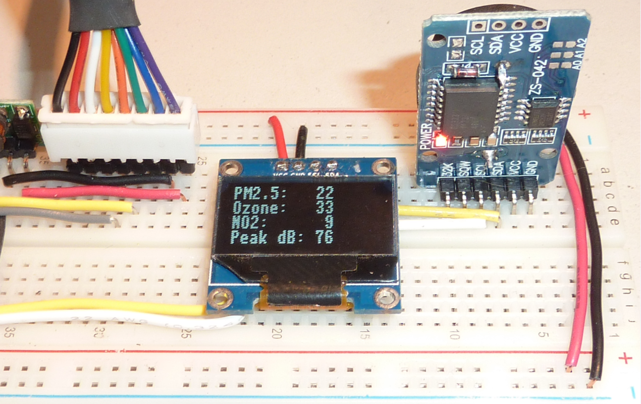
The photo below shows some demo readings on the display. DS3231 clock module is on the right.
The current consumption was measured under different usage regimes
| Condition | Current at Vcc [mA] |
|---|---|
| all pixels off | 0.3 |
| all pixels on | 13.1 |
| "Hello" displayed | 0.44 |
| sleep mode | 0.0087 (8.7uA) |
Discussions
Become a Hackaday.io Member
Create an account to leave a comment. Already have an account? Log In.