 sjm4306
I've known of these types of displays for quite awhile but due to their second hand price on sites like ebay and rarity I just wrote off that I would never be able to reasonable get ahold of them. Then I found out a company based in Poland is still making them so I decided to send an email to Alfa Zeta asking if they could potentially donate some of their small 7 segment displays for this project explaining what I had intended to do with them. I want to make a clock (like everyone else does) but additionally the device would double as a wifi connected subscriber counter for my youtube channel. I figured worst case they would just ignore me but to my surprise within a day of sending that email they replied saying they would be happy to help and were interested in seeing the outcome of my project!
So now I have a generous set of 6 displays coming in the near future. But I need to figure out how I am going to drive them. A lot of the implementation I see end up using discrete components to implement the necessary bipolar control these types of displays require. I decided to make each module control two digits with multiple modules able to be chained together. Instead I wanted to use the cheap, widely available L9110, a dual h-bridge chip meant for motor control. This would simplify component area, wiring and control.
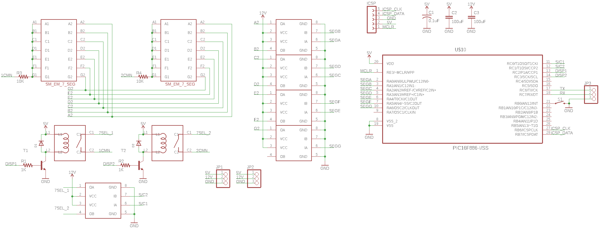
Now since with 6 displays I would have far too many segments to control directly, I opted to multiplex the displays so I have devised a way to drive each of the segments with a single common high side h bridge and an individual low side h bridge. The issue is this will work for a single display but for multiple ones you couldn't control one display without messing with the others, so a high side series reed relay will allow the controller to select each display individually. So parts count so far for a two digit module is 5 dual h bridge chips and two relays (plus some transistors to drive said relays).
The module will require 5V for the digital logic bits and 12V for switching the coils (with onboard resistors to set drive current). The current will hopefully be low enough (~300mA according to the display datasheet) that I can use an off the shelf boost converter module to generate the 12V from the 5V.
For the controller I went with the PIC16F886 since a tiny smd package is available, it has plenty of I/O, 8K of flash, internal 8MHz oscillator and I am well versed in its use. The firmware will internally handle all control of all segments for the two displays and will be easily interfaced serially using a simple addressing scheme which I will thoroughly detail in the next log.
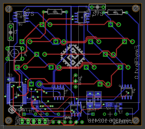
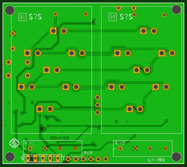
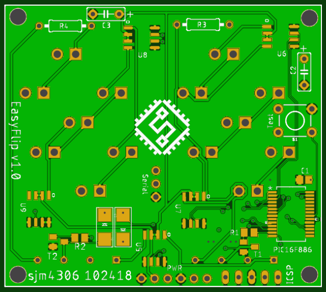
Thanks to my youtube channel sponsor JLCPCB for providing the boards for these modules free of charge. Check them out for 10 pcbs for only $2. So while I wait for all the parts to arrive let's get started on that firmware ...
Discussions
Become a Hackaday.io Member
Create an account to leave a comment. Already have an account? Log In.