 Mark Dammer MM0DQM
There are many ways to get the radio connected and matched to a magnetic loop antenna. Amongst all the army, delta, gamma, toroid and whatsoever feeds the simple inductive loop is widely used. Many sites state that a feed loop with a diameter of about 1/5 of the main loop will give the desired 50 Ohms match for the bands you want to cover. However having experimented with feed loops of different sizes, shapes and diameters in different environments I can say that there is no easy "one size fits all" matching method:
In my experiments the core problem was not so much the loop itself, but the environment. The RF characteristics of a magnetic loop are very much influenced by conducting objects in the close vicinity (~2m) of the loop. This includes not only larger conducting objects like humans, cars, freezers and fridges, but in my case a bicycle parked nearby completely spoiled the SWR probably because the rims of the wheels acted like short circuited loops - no joke.
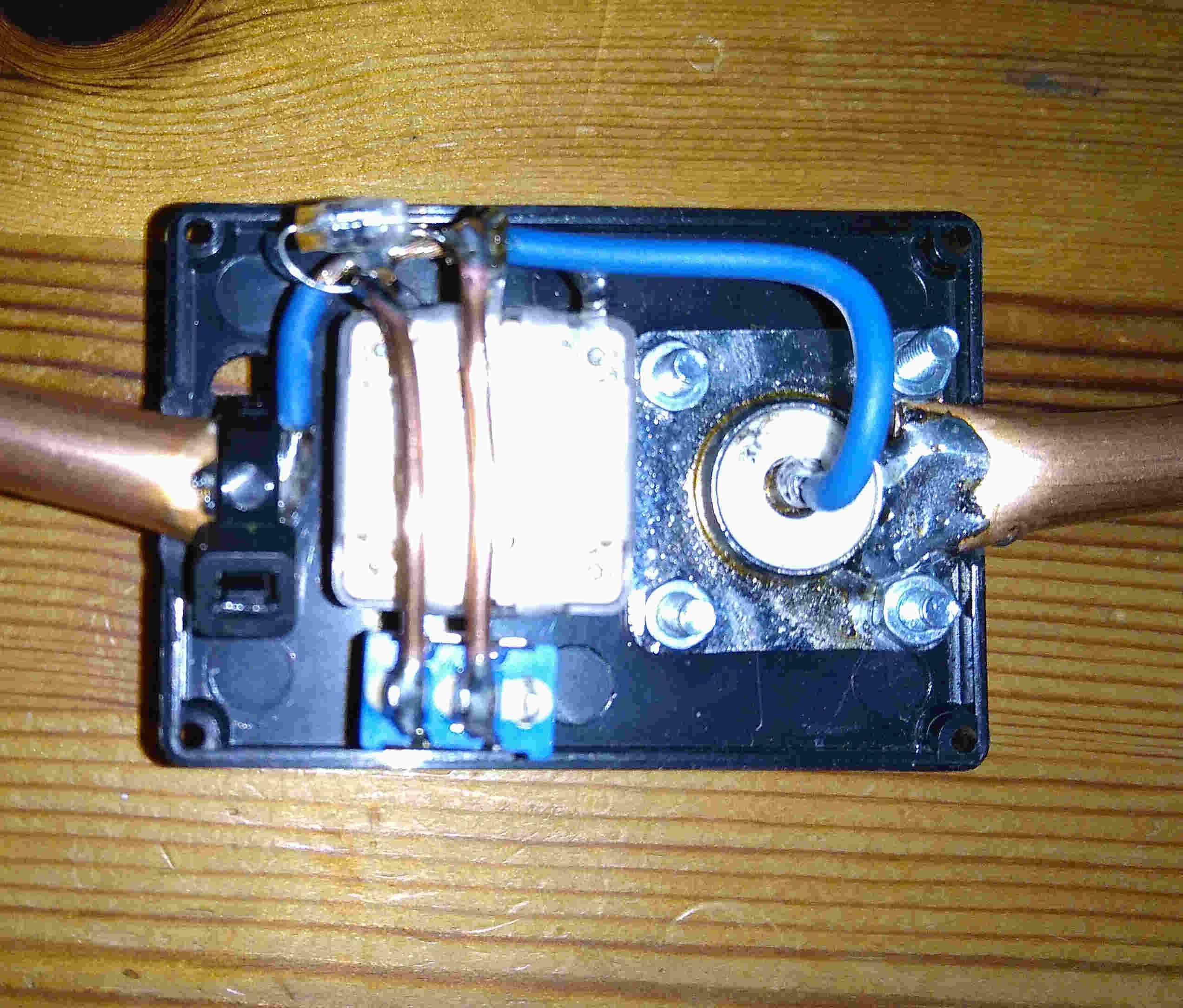
Because I want to be able to match the loop even under difficult circumstances (indoor and almost always "problematic" objects nearby) I put an additional variable capacitor with max. 220pF in series with the feed loop. The little 100pF cap sits parallel to the variable and a switch allows to bridge the capacitors so that the feed loop is directly connected to the radio. With this setup I am able to get a good SWR close to 1:1 even in difficult situations.
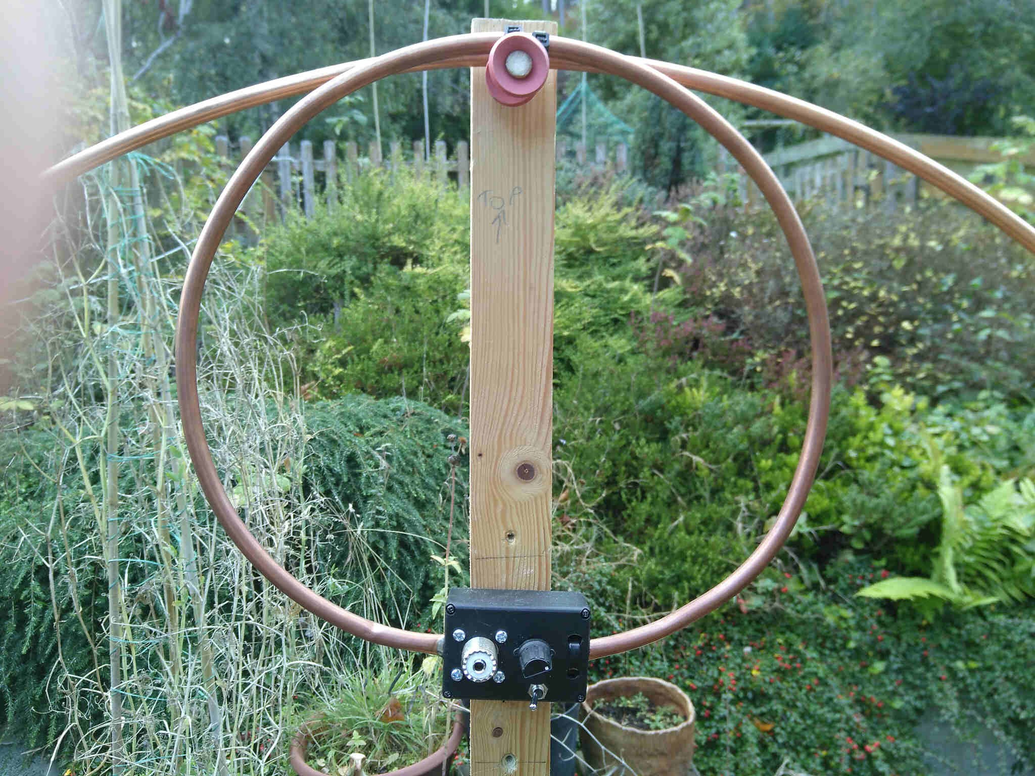
A close up of the main feed loop (Diameter 27cm):
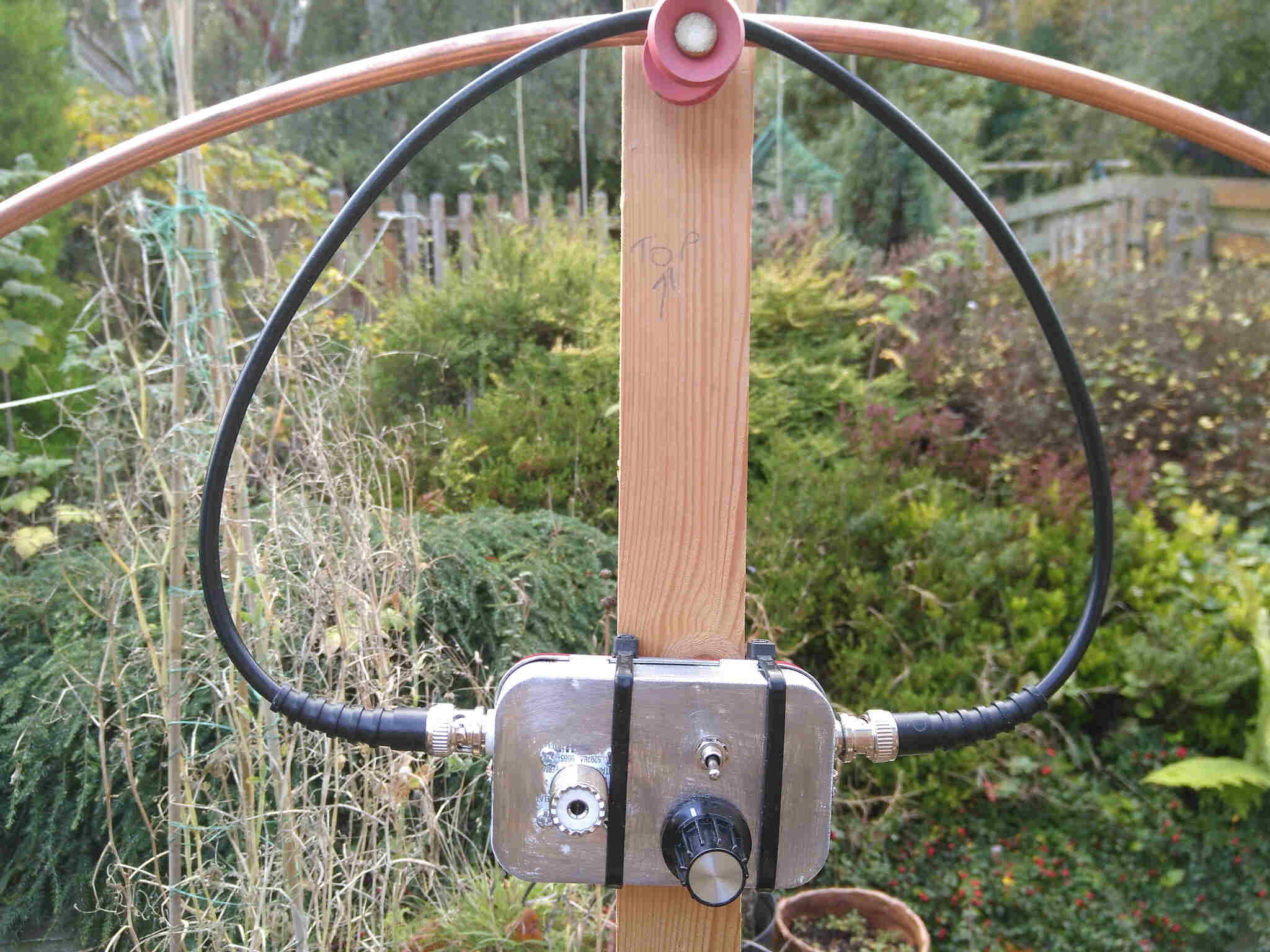
One day I took the antenna for an outing to our T-Exchange makerspace meeting and only got noise and buzzing out of the transceiver. The main reason for this level of QRM was the LED lighting in the venue but the various computers etc. at the meeting added their part to this cacophony. As a consequence I developed a second feed system based on the Faraday Loop:
The circuit is basically the same but this time in a shielding metal box. Simple RG58 cable with BNC connectors forms the loop. While the right BNC socket is the "hot" end of the loop where the core connects to the radio / matching capacitor and the cables shield to ground, only the core is connected to ground at the left "cold" socket and the shield is not connected (notice the insulated socket).
I have seen discussions on the web that question the effectiveness of a Faraday Loop. I have to say that this shielded feed picks up less noise through electrical fields and capacitive coupling. The influence of magnetic noise sources can be reduced by turning the antenna until the noise reaches minimum.
Although this feed improves reception in noisy locations, it comes at the cost of slightly reduced transmit performance. For this reason I have these two feed systems available - one for high performance and one for high QRM environments. In both cases the box containing the matching circuitry is held in place by a velcro strap that runs around the wooden boom. Changing the feed system is a matter of seconds.
Discussions
Become a Hackaday.io Member
Create an account to leave a comment. Already have an account? Log In.