 Stefkuhb
I hooked up my logic analyser and found the trigger source for the controller, it is GDO0 which I found to be connected to TP306! As you can see in the image below it (GDO0 at channel 4) becomes high and after 28 microseconds the controller starts to act.
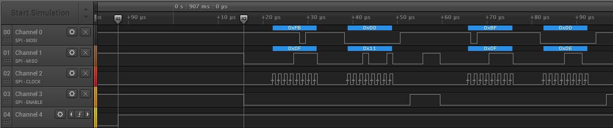
Great! now I can start to think of when the ESP should be listening or when the ESP should be talking. When the system gets powered the MSP configures the CC. when this is done the system goes to idle until data is received from the remote. When data is received GDO0 on the CC becomes high and the MSP responds by making the SS line low and "asking" for data.
So the SS and INT line must be disconnected and fed through the ESP to control something. the other lines MISO, MOSI and SCK can be shared. WAIT! one little problem left: the ESP is running on 3V3 and the CC and the MSP are running on 2V8.
For inputs like MOSI and the CLK we are lucky because the ESP datasheet states that the voltage needed for a high level (Vih) is 0,75 times the supply voltage. 3V3 * 0,75 = 2,475 which is way lower than 2V8 so it can read the inputs.
The outputs like MISO, SS and INT must be lowered to 2V8 and this can be done with a voltage divider. The formula is Vout = (Vsource * R2) / (R1 + R2). To make things simple I choose R1 to be 10K and I want to know R2 so to rewrite the formula to figure out R2. R2 = (Vout * R1) / (Vsource - Vout). So R2 = (2.8 * 10000) / (3.3 - 2.8) = 28000 / 0.5 = 56000. Lucky me an 56K resistor is pretty standard!
Discussions
Become a Hackaday.io Member
Create an account to leave a comment. Already have an account? Log In.