 Ken Yap
Another project using the 8042
Now that the 8042 clock project has been published, I'm publishing another project based on the same hardware. As I stated, the board can be turned to many uses. This one posed some interesting design problems.
I was able to use a large fraction of the code from the clock project, for example the TM1637 driver code was used unchanged, so I only had to solve this design problems posed by this project.
Yes, I know you can get apps for your smartphone that do this and more. But we hack to have fun and exercise our brains. Besides a case could be made for a battery-powered design using a cheap low-power consumption MCU. For one thing you would not get interrupted by social media in the middle of practice or a lesson.☺
Design goals
- Handle tempi between 60 and 236 beats per minute
- Handle the most common metres: 0 (no accent), 2 (duple time), 3 (triple time), 4 (quadruple time), 5 (quintuple time, like in the jazz standard Take Five), 6 (for 6/8 time).
- Make a distinctive sound on the first beat when accent is selected
- Display the current tempo and the current beat
Handling the tempo
This one is a straightforward matter of counting as many ticks (the basic period of work) to get the right tempo. However there are a couple of wrinkles. We do not want every tempo from 60 to 236, the lookup table would be large and it would take longer for the user to set the wanted tempo. We take advantage of the fact that at higher tempi a step of 1 is not as significant as at lower tempi. So we have a scaled table. From 60 to 80, we progress in steps of 1; from 80 to 120 we progress in steps of 2; from 120 to 160 we progress in steps of 3; and from 160 to 236 we progress in steps of 4. In music practice, it is seldom critical to get the exact tempo, we just need to be able to set it approximately. Nobody is going to complain I wanted 83 beats/minute and you can only give me 82 or 84. So instead of storing the tempo, we store an index into the count table. The assembler declarations are generated by a Python script. At the same time we generate a table with the BCD equivalents of the tempo to expedite conversion from decimal to BCD mapping to the 7-segment output.
Incidentally, in this project, the crystal frequency is less constrained than for the 8042 clock. You just need to adjust scandiv in the code to the closest divisor that will give you 4 ms for the tick.
Handling the accent
Mechanical metronomes have a control which turns on accenting of the first beat so that the player knows when to start the bar. For example in 4 beat metre it goes ding! tok tok tok.
At first I designed the firmware to produce a longer beep for the accented beat and a shorter bip for the remaining beats. This is using a self-contained piezo-electric beeper that only requires power, not a waveform.
I tested this and found that although one could distinguish the beep from the bips, it wasn't as good as a real metronome. So I searched for a way to generate a ding electronically. I found cheap sound chips used in toys but those generated sirens and space guns. No way.
In an electronics forum I found this post. This turned out to be a good suggestion. I tested it manually with a piezo-electric beeper and although it didn't have the sharp attack of a bell, the exponential decay did sound chime-like. So here's the circuit I designed. A separate ding pin charges a capacitor which discharges into the beeper for about 100 ms after the pin is turned off.
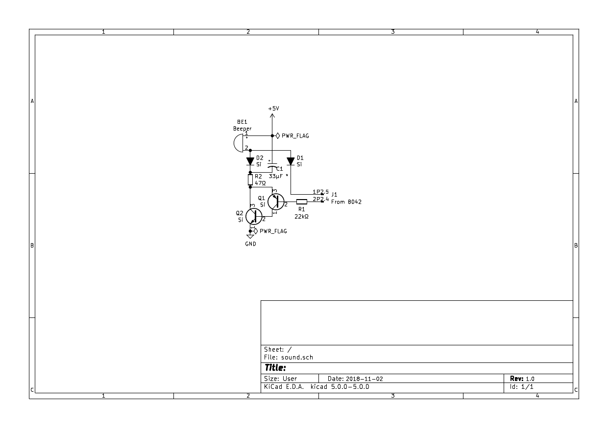
The value of the capacitor marked * depends on the current draw of the beeper. In my case it drew 1.6 mA at 5V. So the equivalent resistance is 3125 Ω. The time for the voltage to decay to 1/e is roughly R x C, so 3125 x 33 x 10e-6 gives about 100 ms, what we want. You should do a similar measurement and calculation to get the value of C.
To charge the capacitor quickly we need to amplify the drive from the MCU. A Sziklai pair of transistors gives high gain. The peak current is when C is totally discharged and a little under 5V is across the 47 Ω resistor, about 100 mA, well within the capability of the NPN transistor. The time to charge should be less than the on period. Here R x C = 1.551 ms. Even multiplying that by 5 to allow for exponential charge, it's still well within the on period (beeplen) in the firmware.
There are shortcomings with this design. There isn't a rapid attack in the envelope like a real bell. The volume is not adjustable. The pitch could be lower. A comprehensive redesign would generate an envelope of rapid attack then exponential decay, to control the volume of an oscillator, and a potentiometer could control the input to an amplifier to set the loudness. On a modern fast MCU the waveform generation could even be done in firmware.
Button operation
One button decreases the tempo, the other increases it. Pressing both together cycles through the supported metres.
Handling the display
I decided to use the same 4 digit serial driven display used in the clock. Fortunately the colon doesn't have to be used and there isn't a wider gap between digits 2 and 3 due to it. The rightmost 3 digits display the tempo, with leading zero blanking. What to show on the leftmost digit? I could show the metre, but that would be not very informative and confusing. For a tempo of say 112 beats/minute and a waltz metre, this would show 3112. That would be confusing to a music student or teacher. I thought of getting a wider display, even a 16x2 LCD one, but I didn't feel the extra display was justified.
Then I hit on the idea of displaying the current beat number, not as a digit, but as a segment animation. The best way to understand this is to look at the video.
https://cdn.hackaday.io/files/1621596937810656/metronome.mp4
The video shows changing from a 4 beat metre to 5, then 6, then no accent, then duple time, then triple time, and finally back to 4 beats. Then increasing the tempo, and decreasing it. Notice that on metre change the display silently shows the final beat for one period before beginning the animation, giving the user feedback what metre is selected.
Limitations of this design
A modern MCU would be a better choice for a redesign. It would consume less power and also take up much less space.
As mentioned before the sound is not ideal. A better sound generator is needed.
The 8042/8048 architecture limitations show up in another aspect. It is not possible to extend the tempi below 60 as this would require divisors > 256, and the timer counter is only 8 bits. A later MCU, the 8051, has 16 bit counters. We could increase the tick period but then the divisors at the faster tempi would be small and resolution would be poor. Also the resolution of the bip and beep periods would be affected. In addition, extending the tempi tables would make it overflow page 3 (an 8042 page is 256 bytes). Though higher pages can be used as the 8042 can address up to 2kB of program memory.
Cycling through the metres is not ideal. There should be up and down buttons like for tempo. The most commonly used metres are 2, 3 and 4. Then perhaps no accent. 5 and 6 are not often used so there is no good reason to make the user go through them to get to other tempi. It's all because I didn't want to dedicate another pin for the extra button. In fact traditional metronomes seldom have 5 and 6. Teachers often treat 6 as duple or triple time, depending on the piece.
Conclusion
I might revisit this design when I move on to the MCS-51 or AVR MCUs.