0%
0%
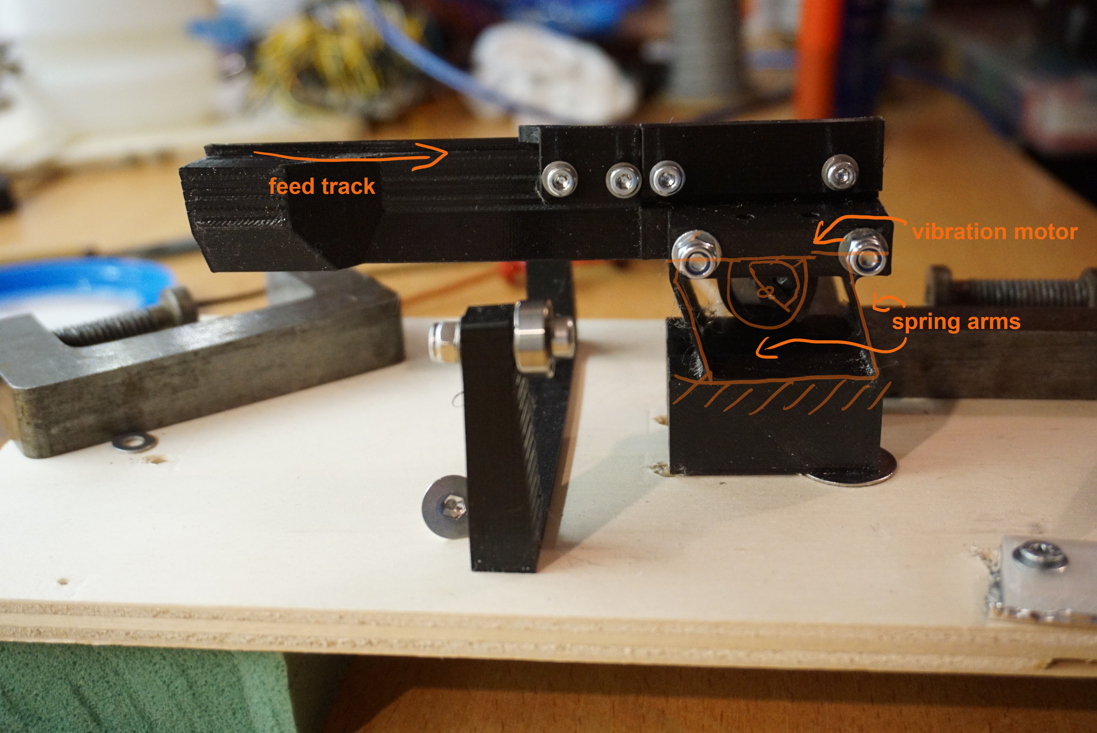
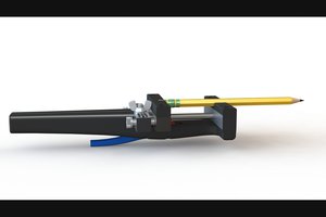
DIY Drum feeder
Automatic supply of small parts
Become a Hackaday.io member
Already have an account? Log in.
Just one more thing
To make the experience fit your profile, pick a username and tell us what interests you.
Pick an awesome username
hackaday.io/
Your profile's URL: hackaday.io/username. Max 25 alphanumeric characters.
Pick a few interests
Projects that share your interests
People that share your interests


 Alex Rich
 Sam Baker
 Sci
Sci
I can't help but think "Next, on How It's Made"... these kinds of assembly automation tricks are among my favorites!
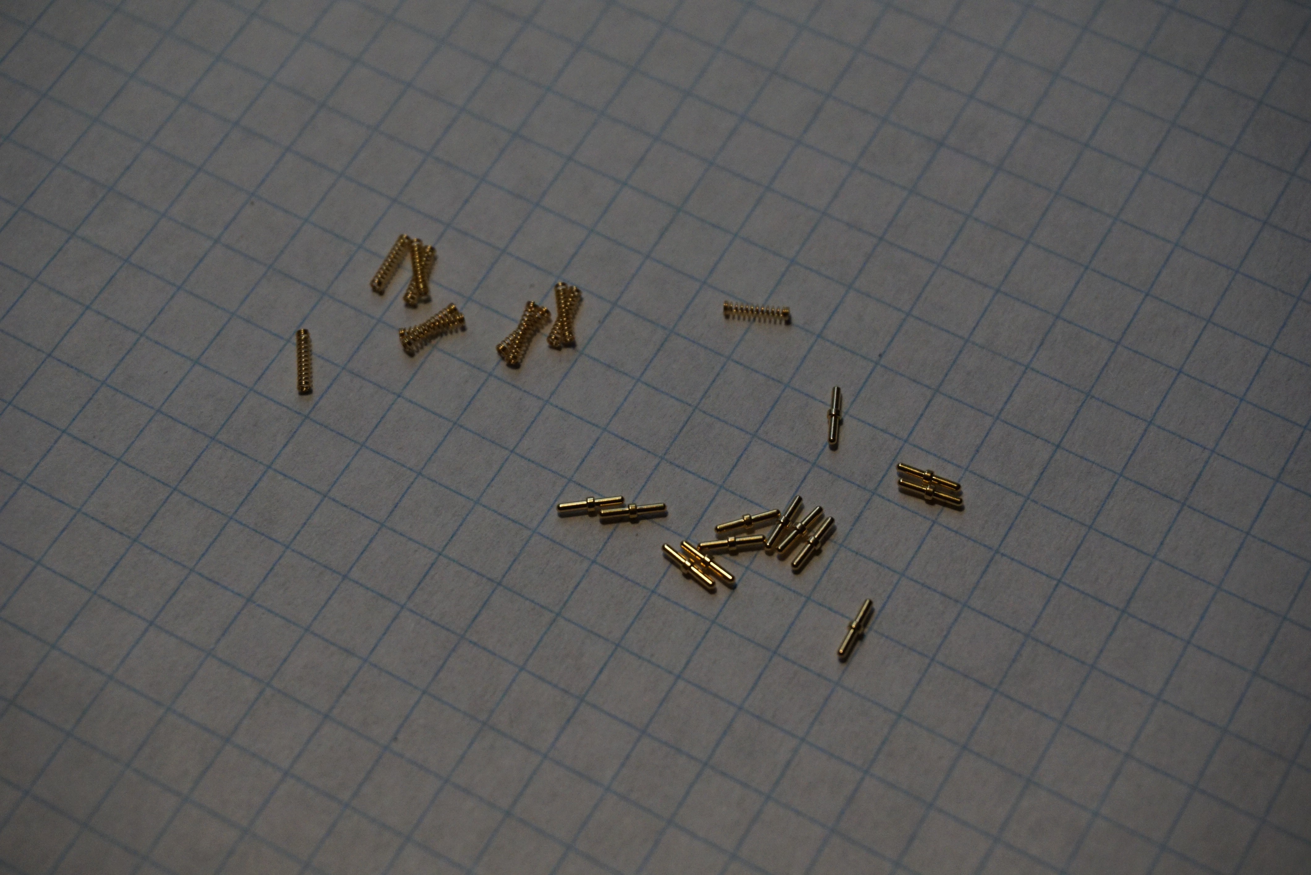
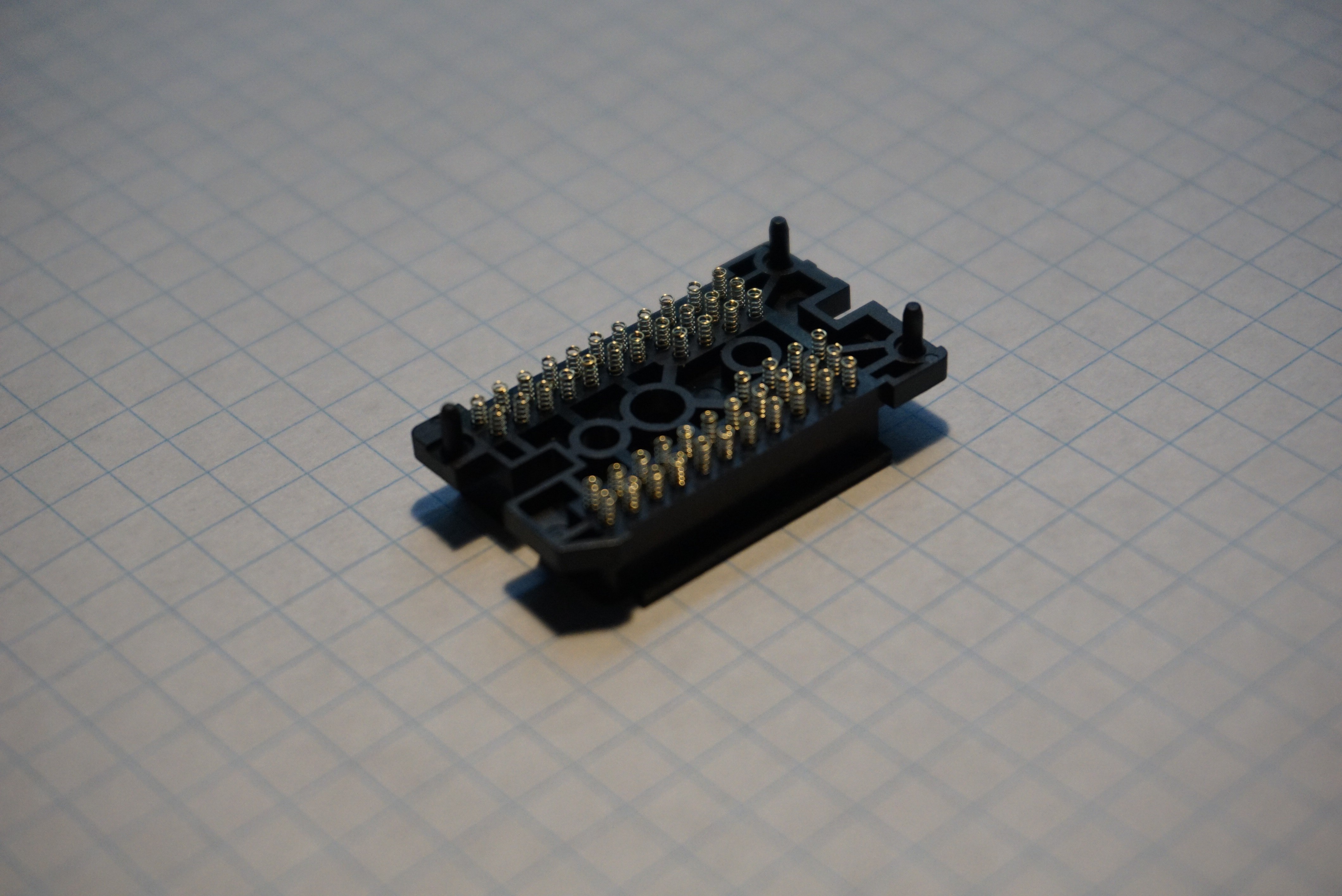
Can't wait to see how you solved this. I can't quite envision how this get automated? Do you still have to place each spring by hand, but this separates and orients them saving the fiddly bits of it?