 Andrew
Introduction
Hey! Thanks for checking out this tutorial, I hope you find it useful and if you have any recommendations, questions or comments, please reach out!
I am one of the organizers of a kickass group NeuroTechLA, the Los Angeles chapter of NeuroTechX, a global network of engineers, designers, scientists, and hackers driven to learn and push forward the boundaries of bona fide neuroTechnology. If you're new to this field and interested in getting started with brain-computer interfaces (BCI) or electroencephalography (EEG), checkout NeuroTechEDU's GitHub repo of awesome list of BCI-related resources. Or, attend one of the events that we might be holding in your city!
This tutorial is the result of our chapters desire to do BCI-related projects with Muse headsets. Specifically, we wanted our chapter to go through workshops like this P300 ERP Juypter Notebook experiment using an extra electrode and many more. There were a few tutorials and forum discussions on how to make these extra electrodes, but I found them a little bit incomplete and inaccessible.
Lastly, special thanks to Interaxon, the company responsible for the Muse headsets, for donating a couple headsets to our chapter! They, along with the many members of NeuroTechX, made this possible.
Disclaimer
- This is not an official Interaxon tutorial;
- DO NOT plug the electrode into a power source;
- Use caution and be safe!
Goal
Our goal in this tutorial is to connect an EEG electrode via a male Micro USB connector to the auxiliary input of our 2016 Muse headset (the back right of the headset where you would charge the device) so we can access EEG (or EMG / ECG, etc.) data.
We will do this by removing the safety jacket and exposing wire from our lead EEG cable, solder said wire onto a 5-pin Micro USB connector, wrap with heat shrink, snap the Micro USB plastic covers on, attach hook & loop fasteners to our headset for keeping the electrode stable while recording, snap on a electrode to our cable lead and test using Python and the muse-lsl library.
Instructions
Note: We assume you know how to solder, or you know someone who can help you. If not, soldering kits are ~$30 on Amazon.
Step 1
- Purchase and gather necessary supplies and equipment.
- Below is a photo of everything I used (Muse headset, 3rd arm clamps for soldering and wire cutters not shown).
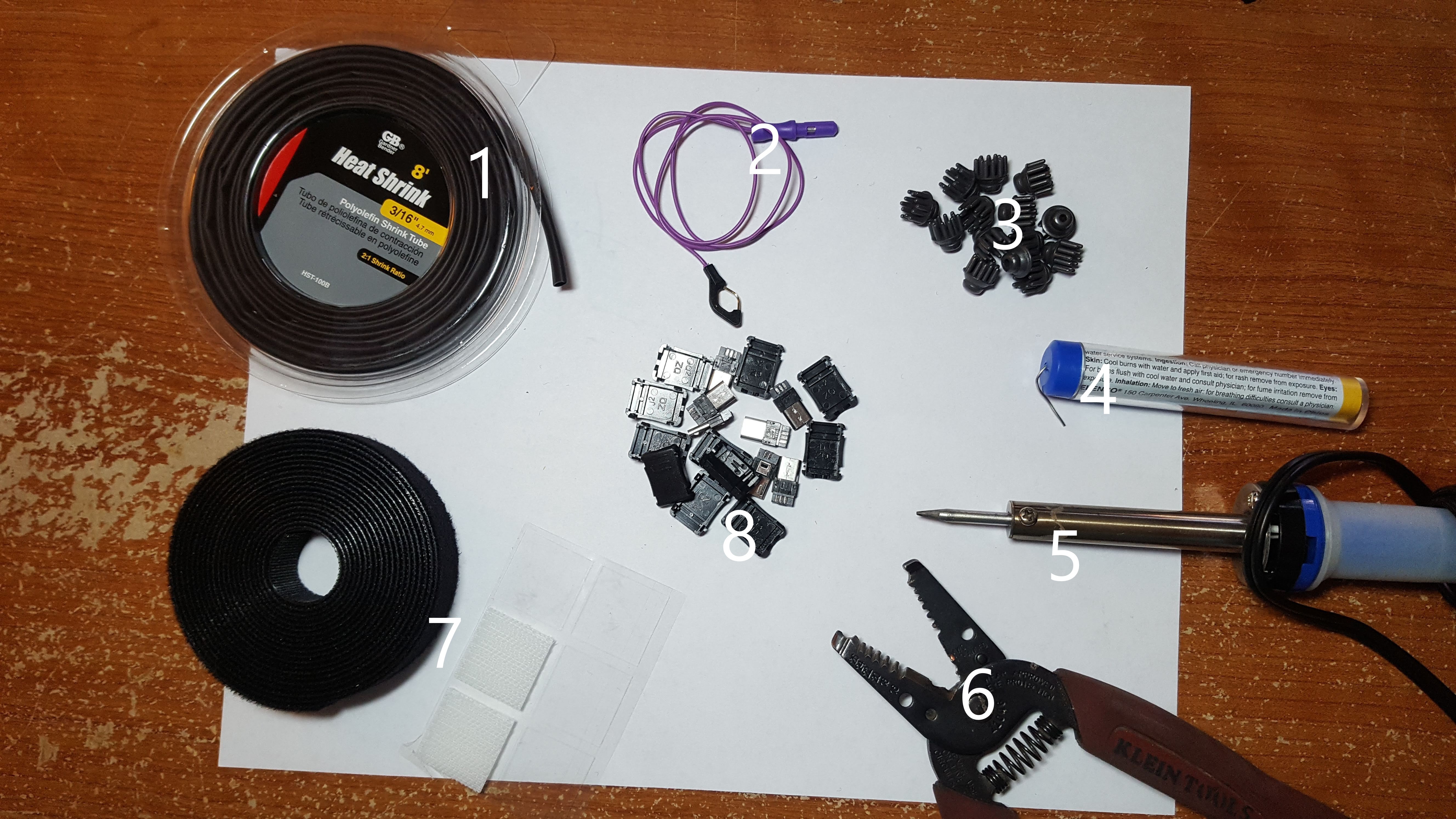
- Heat shrink for wrapping the Micro USB connector in
- Lead wire for EEG electrodes
- Since we are only removing the safety jacket (the end of our wire) we can use any electrode wire such as an OpenBCI snap electrode cable, gold cup cable, etc.
- In this tutorial, we will be using a lead wire designed for snapping on dry EEG electrodes as shown above.
- EEG dry electrode (pack of 10+)
- As noted above, we could have used gold cup electrodes (which can be referred to as wet electrodes which means they would require conductive paste), or EMG / ECG foam solid gel electrodes that would have been used with snap electrode cables.
- In this tutorial, we will be using dry EEG electrodes that will snap onto our lead wire.
- 60/40 Flux Core Solder
- Soldering Iron (best practice is use a temperature controlled soldering iron, the one shown above is not)
- Wire Strippers
- Hook and loop (think Velcro) straps
- Shown in the photo as a roll next to the adhesive hook and loop stickers.
- 10 Piece 5-Pin Micro USB Type B Male Connectors with Plastic Cover Kit
See the components section in this project for details on where these items where purchased and the costs.
Step 2: Wire Preparation
Take your EEG lead wire and remove the safety jacket (circled in green) by giving it a tug, which should expose about 1 to 7 mm of wire. Or cut close to the safety jacket and use your wire strippers to expose the wire.
- Note: At any point in the following next steps should an error arise (like using too much solder, etc.) simply snip off the wire, use your wire strippers to expose a little bit of wire and come back to this step.
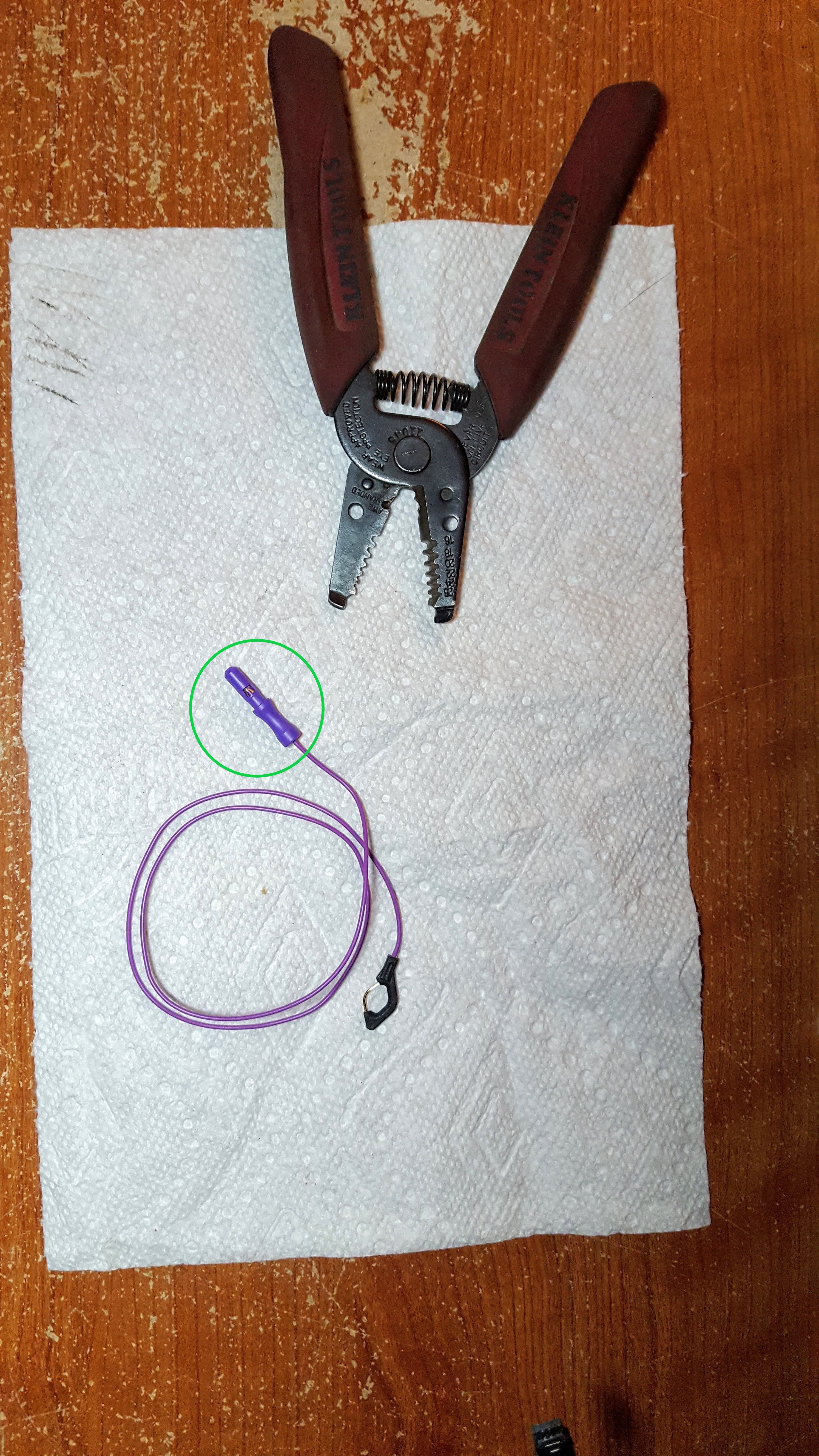
Secure the wire for the next step and if applicable snap your EEG electrode on.
Step 3: Soldering to Micro USB
Now, the next step will be to solder the exposed end of the wire to a male Micro USB connector. According to Sam from Interaxon, this connection needs to be made specifically on pin 4 on the Micro USB 5-pin layout.
But where's pin 4?
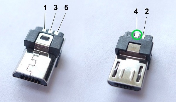
Cool, that's pin 4, but what do these pins mean? According to Wikipedia:
| Pin | Name | Wire color | Description |
| 1 | VBUS | Red | + 5 V |
| 2 | D- | White | Data- |
| 3 | D+ | Green | Data+ |
| 4 | ID | N/A | Permits detection of which end of a cable is plugged in, "A" connector (host): connected to the signal ground, "B" connector (device): not connected |
| 5 | GND | Black | Signal ground |
I think we can intuitively understand data, ground and power, but ID? (Though D- and D+ are kinda confusing so here's a nice description of Data+ and Data-)
According to this StackExchange answer, this extra pin which is used as of late 2001 is also called On-The-Go (OTG) which is used to select which device is the host or slave, or as Wikipedia puts it,
USB On-The-Go, often abbreviated to USB OTG or just OTG, is a specification first used in late 2001 that allows USB devices, such as tablets or smartphones, to act as a host, allowing other USB devices, such as USB flash drives, digital cameras, mice or keyboards, to be attached to them. Use of USB OTG allows those devices to switch back and forth between the roles of host and device. A mobile phone may read from removable media as the host device, but present itself as a USB Mass Storage Device when connected to a host computer.
So in short, we are using pin 4, or the ID, as a way to tell our Muse headset to play host to our new electrode.
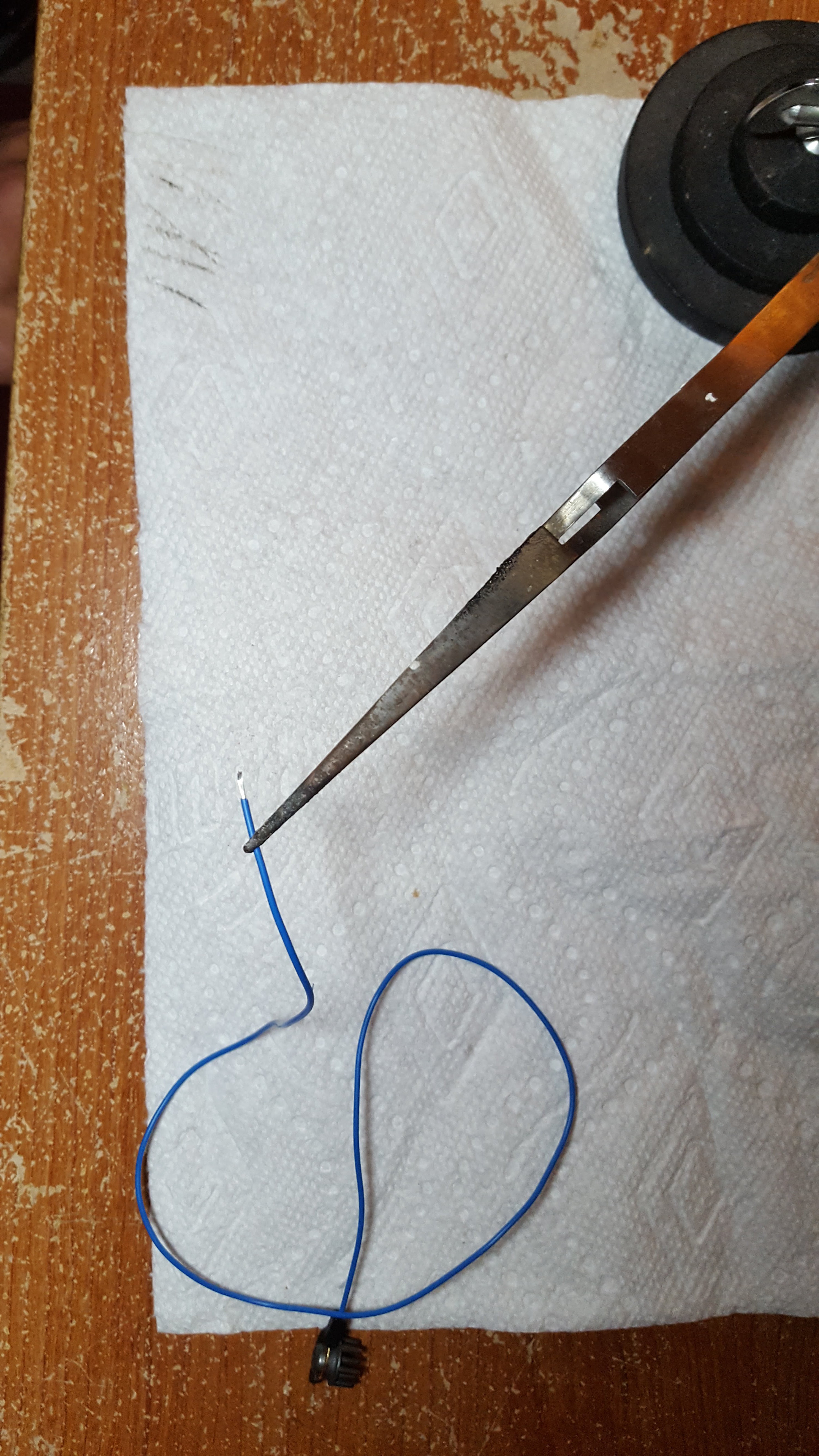
Soldering
These pins are small so soldering is tight. There may be a better method, but below is how I did it. Additionally, if you purchased the 10-piece Micro USB kit, I recommend practicing on a couple pins with some old wire.
- Consider using 60/40 Flux Core Solder Lead/Tin solder which is easier to use in almost all cases.
- Wear a disposable respirator with at least a P100 rating (3M P100 Disposable Respirators on Amazon are under $15 per mask) to protect your lungs from the metal infused smoke that comes off of hot solder. A P100 rating will filter out 99.97% of pollutants, dust, and solvents from the air.
1. Add solder to each of your individual wires first.
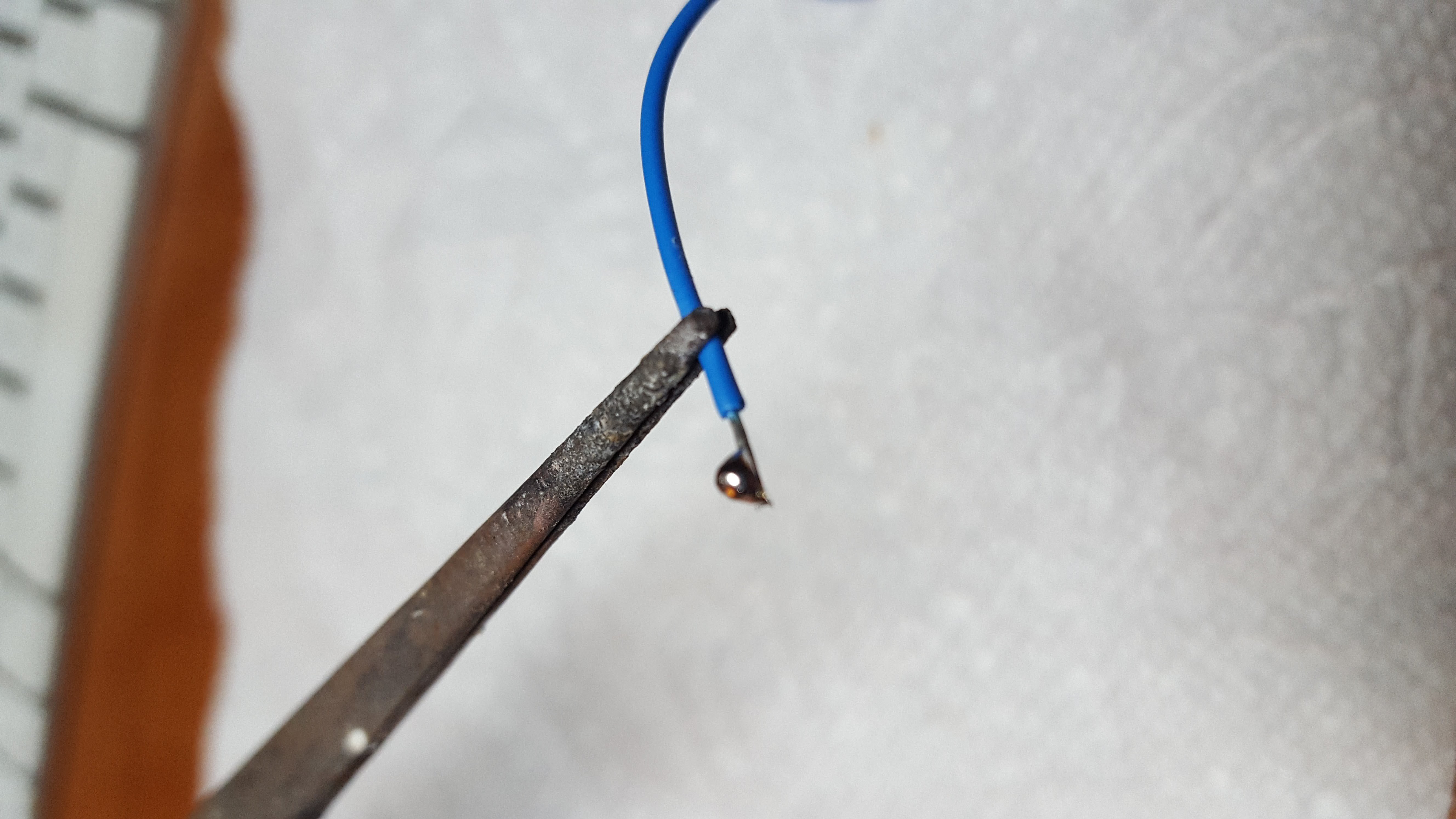
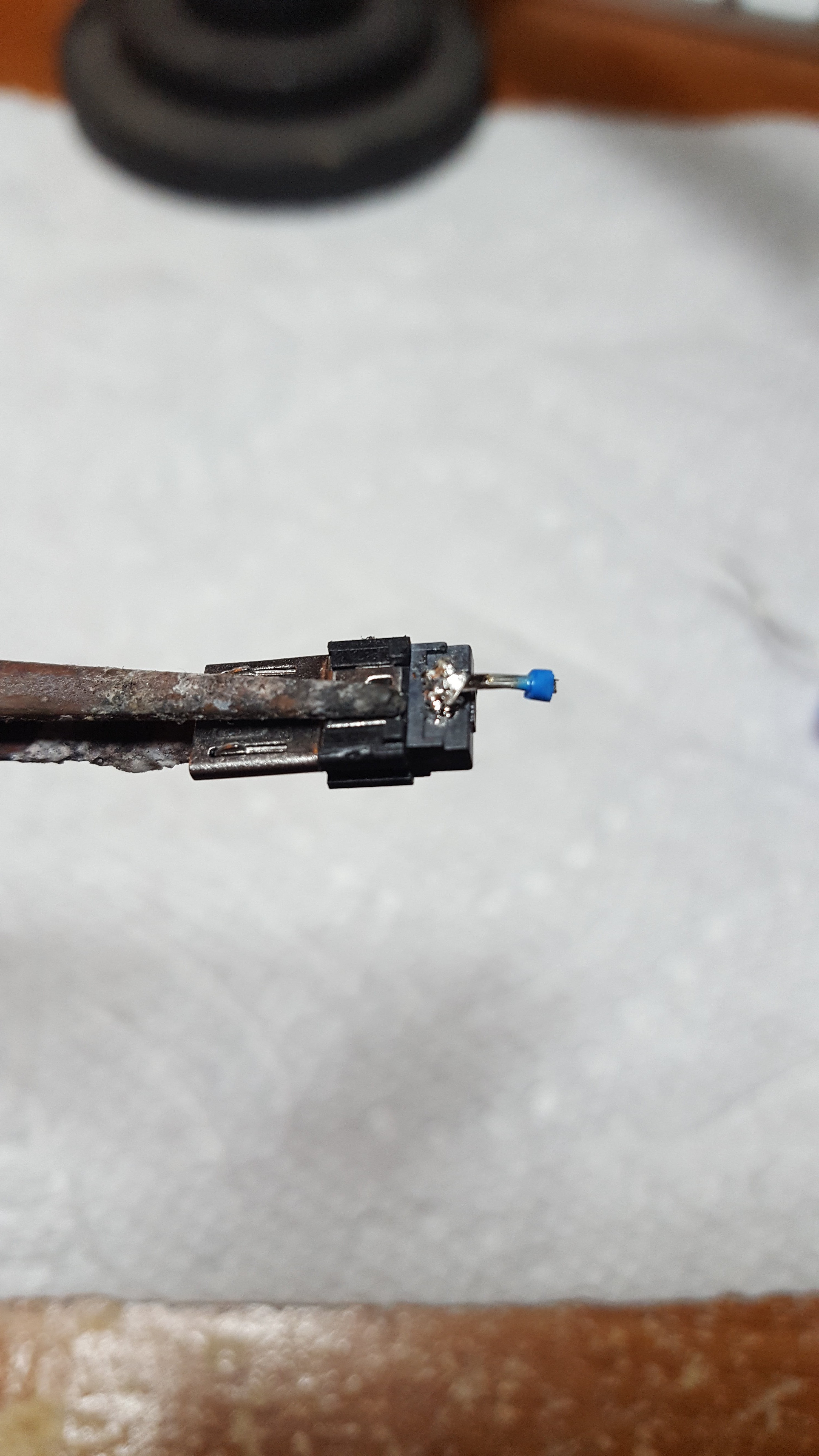
2. Then, touch the wire to the corresponding pad. And touch a hot, fine tip, soldering iron to the wire so the solder in the wire can heat up and adhere to the pad.
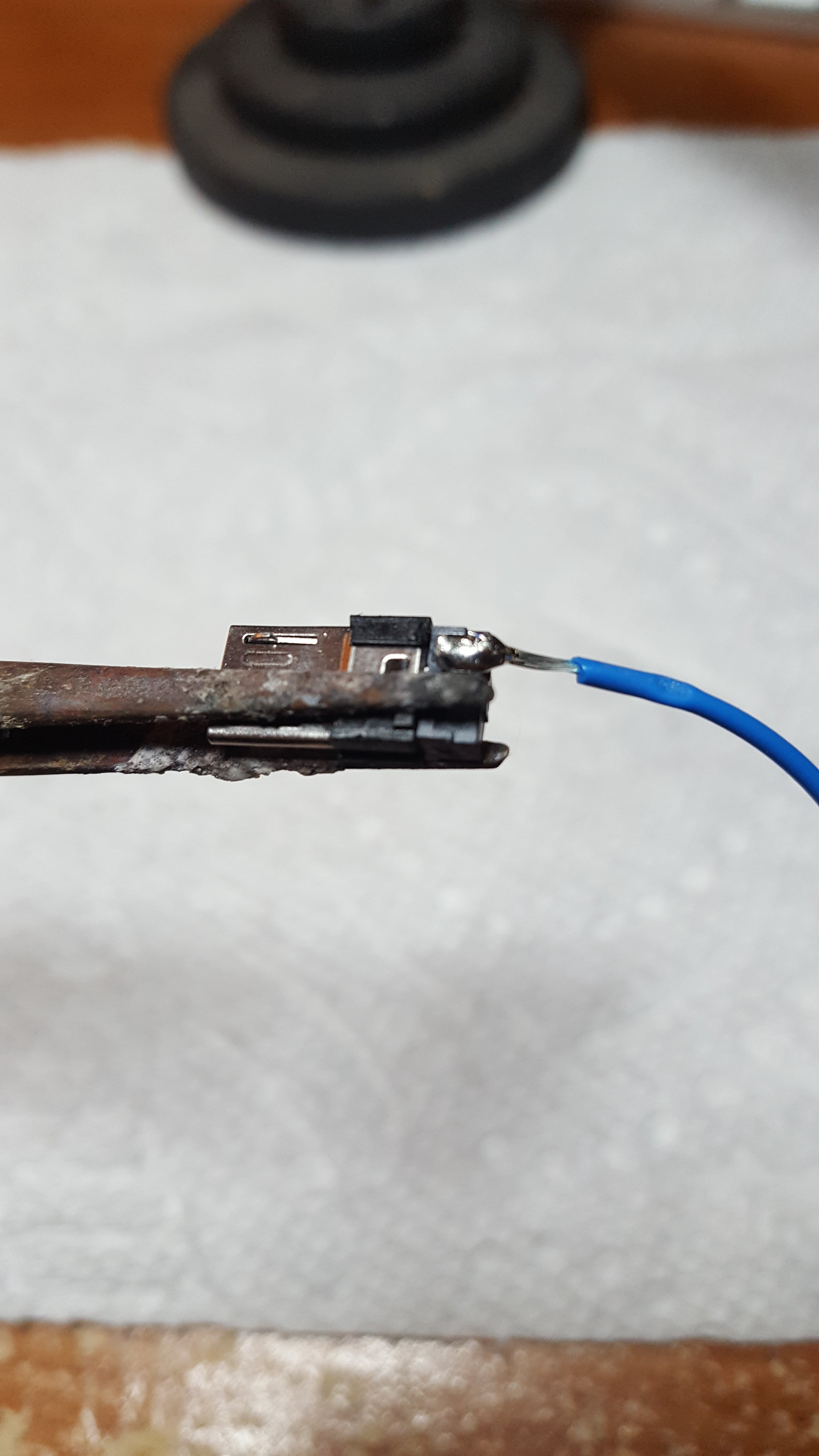
And we should end up something like the following photo below.
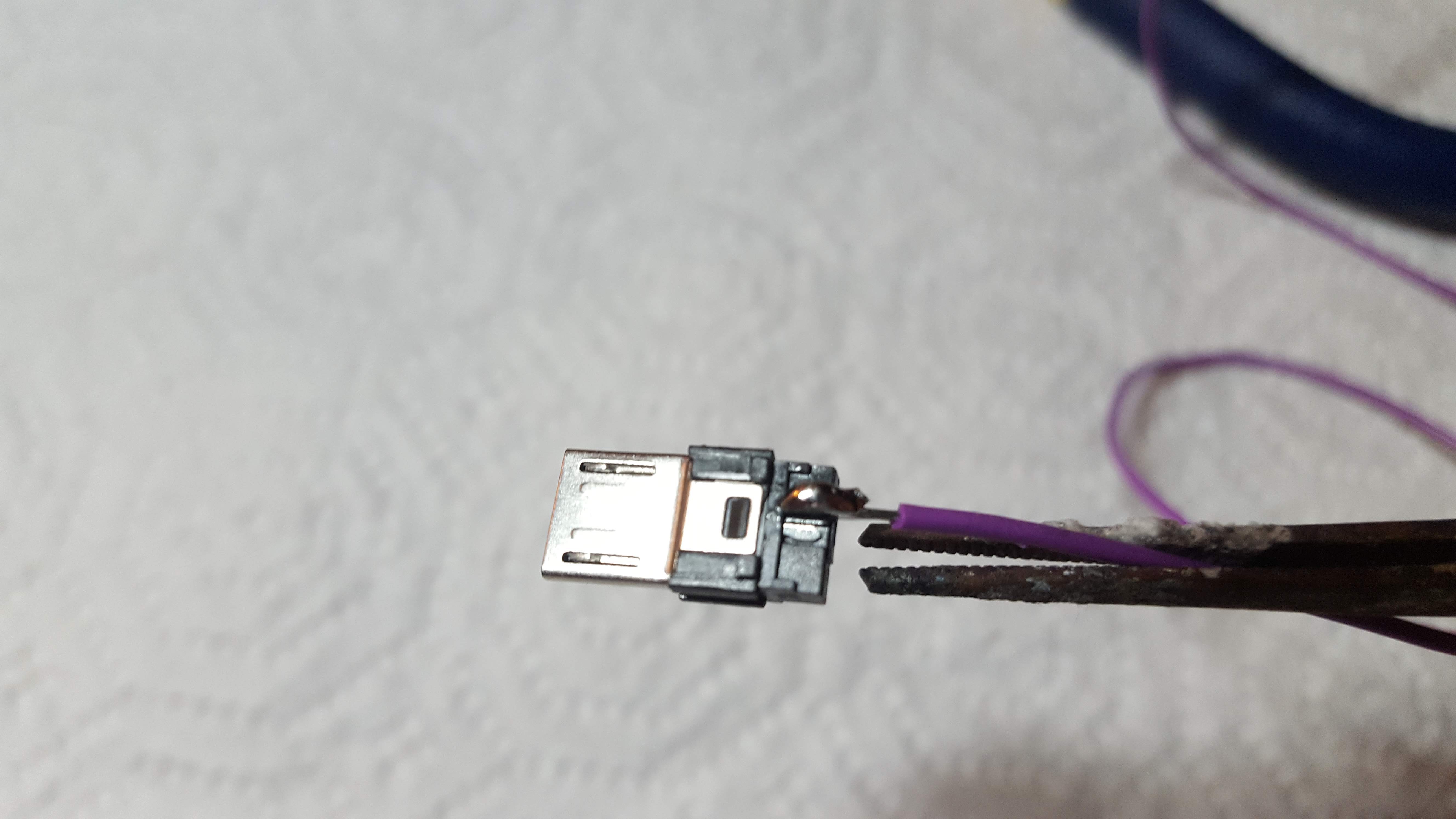
Below is a photo of a blunder I made where my hand slipped and I got solder on pin 4 and pin 5 - not good, so I cut close to the wire, exposed some more wire and gave it another go.
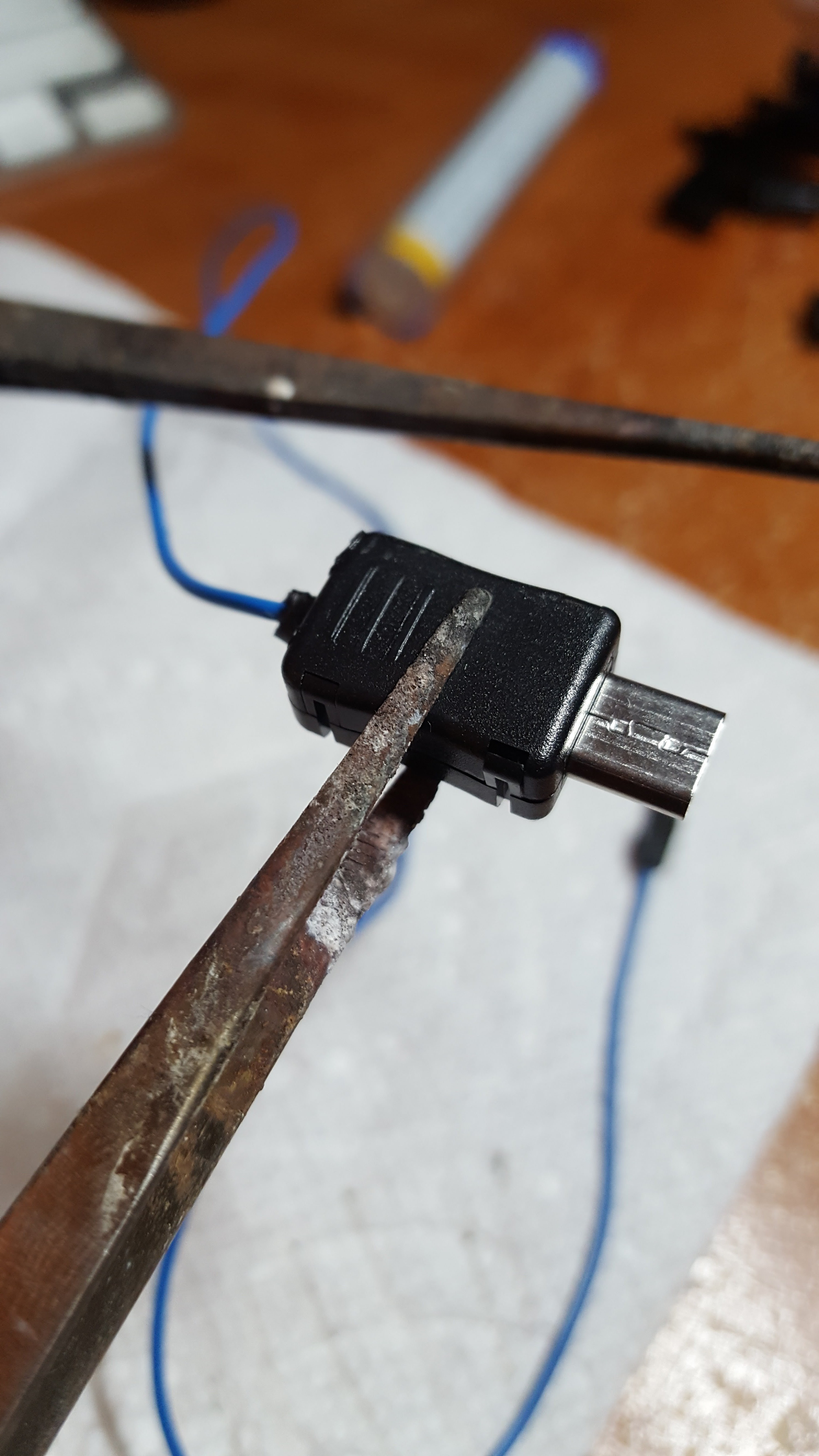
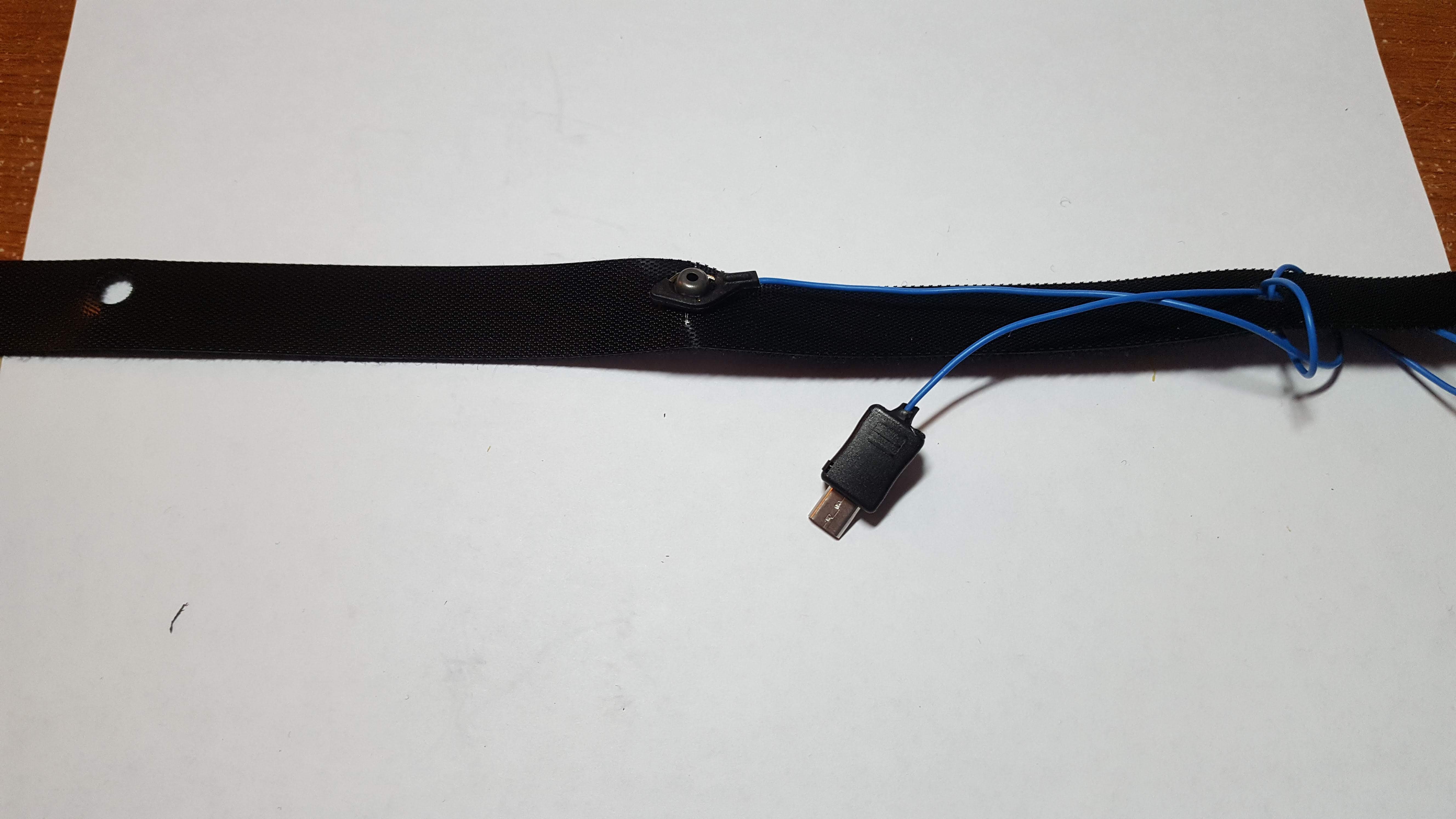
Step 4: Heat Shrink and Plastic Encasing
Once soldered together, wrap the heat shrink around the Micro USB so it sticks out a little when clipping together the plastic encasing.
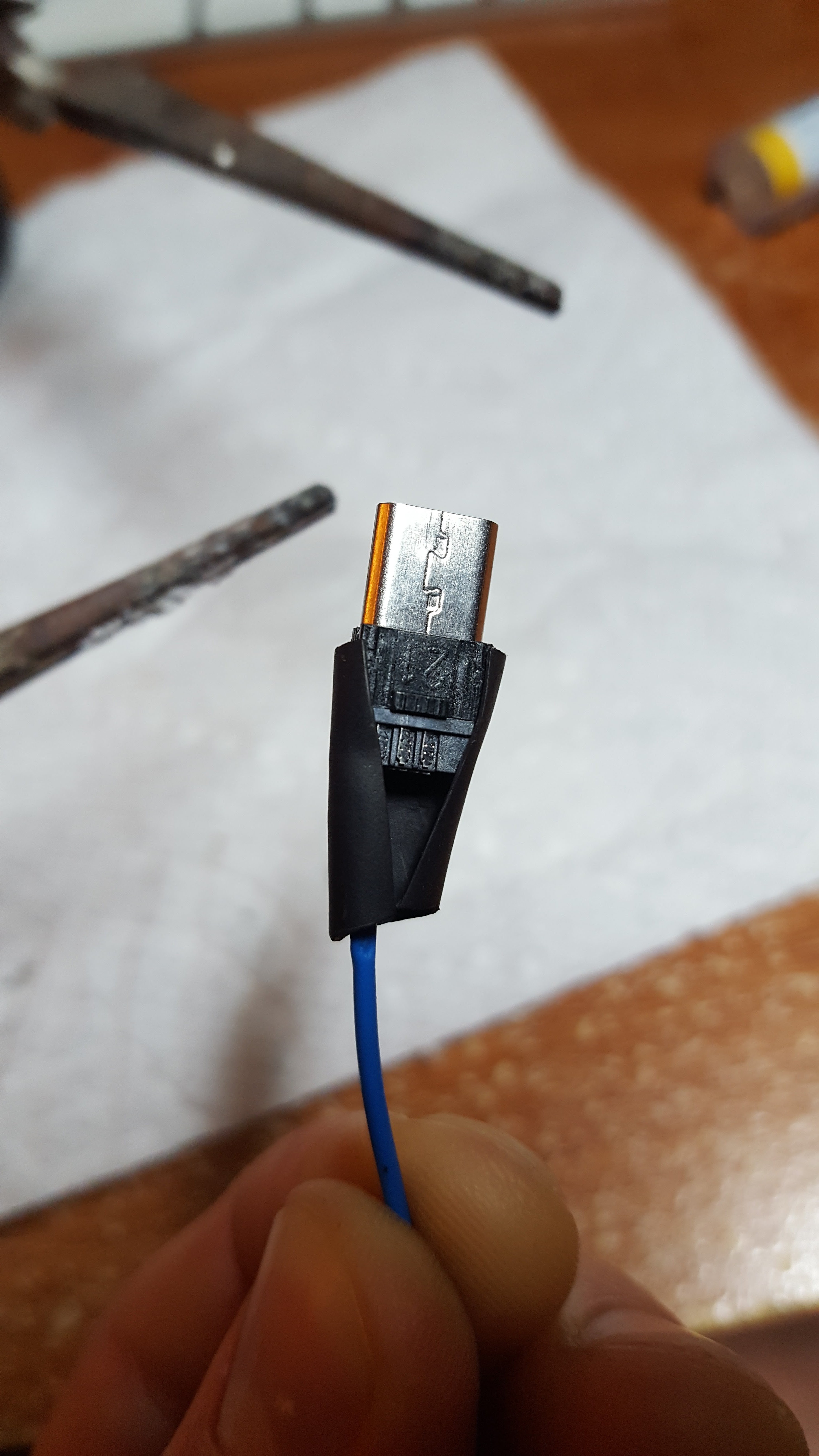
Then use the soldering iron for shrinking the heat shrink (I'm not sure if this is necessary, but it looks nice), and finally clip the plastic encasing pieces together.
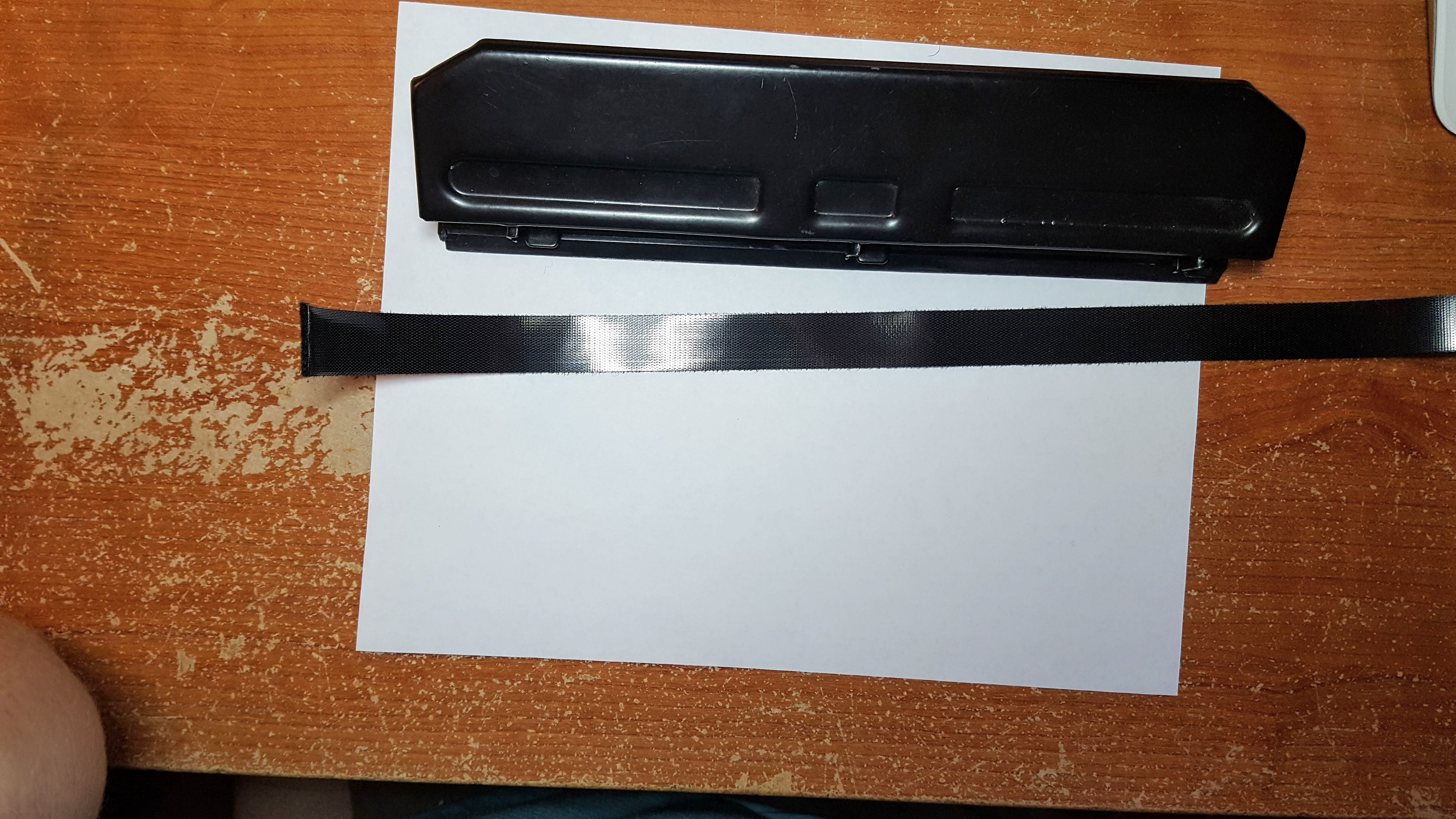
Step 5: Hook & Loop
Next, we’ll make a simple strap that will help us hold our new electrode in place on our heads!
Take your roll of hook and loop and cut about 20 inches off. Find the middle by folding it in half and mark it by using a hole punch.
Note: I used ~20 inches because I wanted to play around with it, but 12-15 inches will probably look more "fitted."
Not shown below, but peel off your square hook & loops and stick those onto the sides of the Muse headset for the strip you are about to cut to "hook" onto (see final image with the white squares on the side of the Muse headset).
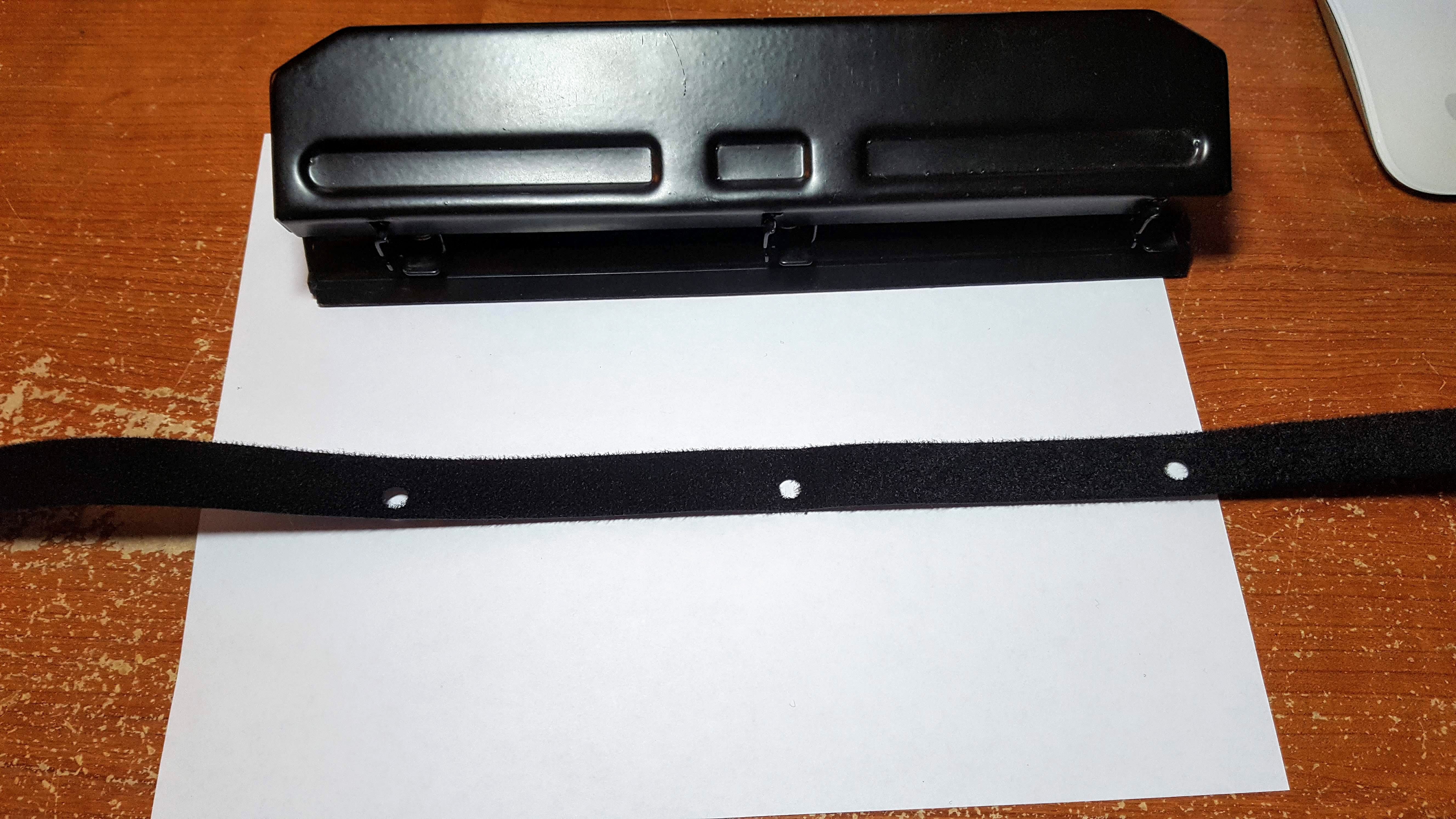
Kind of hard to tell, but the photo below has the electrode inserted in the middle hole ( you might have to cut a little on the sides of the holes with some scissors to get the electrode to fit snug).
Wrap the excess wire in the unused holes so it's tucked away.
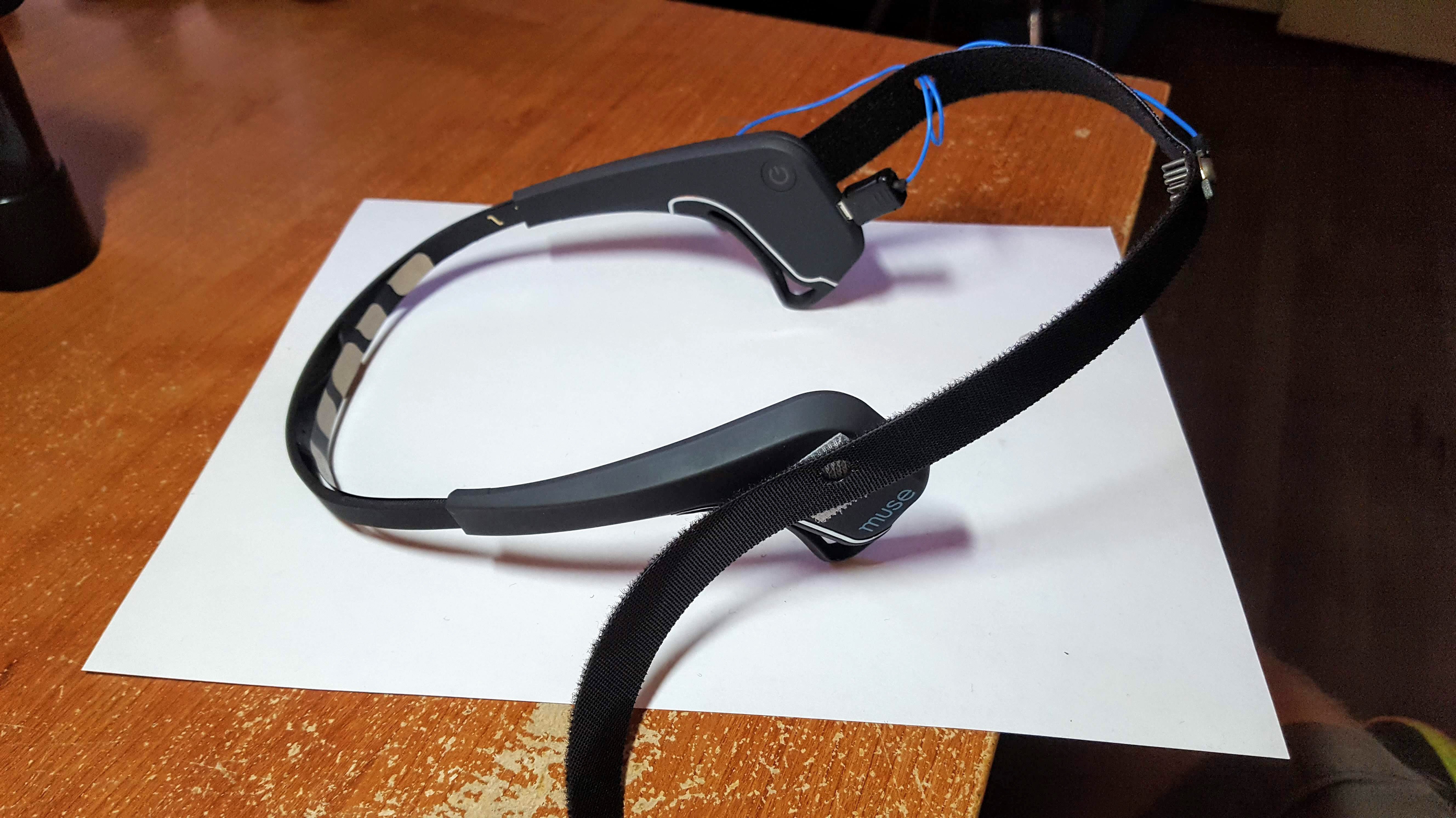
Step 6: Attach Hook & Loop To Muse
With the 10-20 placement in mind, Oz (directly back of the head) or Cz (directly top of the head) are configurable with this setup, but in theory you could get weird, make more holes, and configure accordingly. Go wild.
Step 7: Connect, Test / Muse-LSL
Not going to go into the details of how to connect your headset to your computer as there are way better tutorials out there for that, like this, or this one for Windows.
The important thing is that the "Right Aux" channel should correspond to the extra electrode that we've constructed. Once you've applied it firmly to the head with the strap, ensured connectivity through hair, and let things settle for a while, it should display a signal that looks similar to the four main Muse channels.
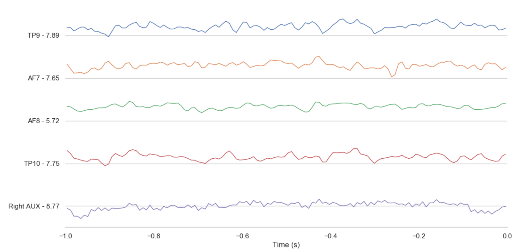
Congrats! You've extended the capabilities of a Muse headset and are able to implement more of the classic EEG BCI paradigms such as P300 and SSVEP!
Have fun! And if you have any questions, comments or suggestions on the above steps, please feel free to reach out.