Punched Tape Reader Peripheral for 8008 Emulator
It occurred to me that I could build a tiny paper tape reader for my 8008 emulator (see https://hackaday.io/project/161404-videops2-keyboard-8008-system-emulator). I have some mechanical paper tape readers I've resurrected from industrial equipment combined with new electronics, and a few punches. But I wanted to build a purely optical, pull-through reader from scratch that would match the size of the 8008 emulator.
This is one of those projects that seems conceptually easy, but actually building it was physically challenging for a lot of reasons.
Punch tape works in a 0.1" universe, which is still the way that I work, mostly in the pre-surface mount era. So, my plan was to make an optical head with photo transistors and big 1206 surface mount infrared LED's shining through/reading through one side plated-hole prototyping board. The appropriate nine holes (one for the sprocket/timing hole, 8 for the data) would be drilled out to the size of the paper tape holes. Vishay BPW17N optos were used. Note that common 3mm LED's and optos won't work for this application, because 3mm x 9 = 27mm, and the tape is 1" wide (25.4mm).
I made a sandwich of boards, optos on the bottom, LED's on the top, with a very thin spacer of thin PCB fiberglass material taped to the board with double-sided tape like that used on modern Apple equipment. Alignment was crucial, and I was careful to solder the LED's so that the die wound up in the center of the holes. A flashlight helped me align the boards during taping, showing through the three-board optical perfboard sandwich.
The bottom board, which plugs in, contained the HC165 which would relay the data back to the ESP8266. The principle was, the small timing opto hole lets light through last after all of the other holes (if any) have lined up. Upon the falling (rising) edge of this, the HC165 data is latched and the ESP8266 is interrupted, and then the ESP8266 clocks the data out of the HC165. i wrote a test program on an ESP8266 to help me debug the hardware.
The recommended way to do this, with optos being analog devices, is to use Schmitt triggers, but the ESP8266 doesn't have this as an option for I/O. I THOUGHT I could do this anyway with careful interrupt timing. Boy, I was wrong. It didn't work no matter what I did.
So, the electronics board was replaced with a board with the HC165 and two 74HC14's (hex Schmitt triggers). Due to space limitations (the box was already made), I could not use sockets and had to point-to-point these with wire wrap wire (VERY nasty). This worked, finally - sort of!
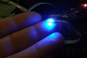
I really didn't give much thought to the brightness of the LED's or the sensitivity of the optos. The optos went through 2k resistors, which made them highly insensitive. Worse, the "tiny" 1206's were amazingly bright. Of course, you can't see the IR from them, so I used a GoPro clone camera with no IR cut filter to view them. They were incredibly bright. I had to put a 500 ohm pot (not good practice) to vary the brightness from very bright to nearly fire-starting. NOTE: Doing this, I discovered that modern phones/cameras all have IR cut filters and you can't use them anymore for detecting IR (like, from a remote).
I made "test tapes" with my punch. These tapes were basically each bit repeated, then the "not" versions of each bit repeated, then alternating patterns thereof. I was testing for "show through" and "crosstalk" in addition to getting the hole/no hole levels right. Although I found a brightness level that allowed Mylar and black paper tape to work, my "gray" DECtape and cheap yellow fanfold tape did not work, and no adjustment to LED brightness would help. Show-through was a problem, both with the tape and also with the green perfboards themselves.
Getting this in a case was also a challenge. Wood rails were made to slide in the assembly, and front/back pieces were made from aluminum...
Read more »
 Morning.Star
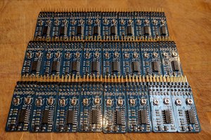
 Idris
Idris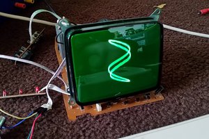
 Emily Velasco
 arturo182
They pull very easily at even fairly high speed, and have enough friction to stop them from going backwards. A small (non-stepper) motor with a shaft and some pulleys with o-rings could probably work through a slot on the top board. I didn't pursue this because I've bought fairly inexpensive stepper-fed paper tape readers on eBay and swapped out their electronics with interfaces more to my liking. Those are much easier for loading longer programs - but those units are larger, of course.