Close
0%
0%

Supercon Badge Surface Plotter

Firmware hack for real-time animated 3D surfaces

Similar projects worth following
I wrote a lot of this Supercon 2018 badge hack on a plane from Chicago to LA. It draws real-time animated 3D surfaces with hidden-line elimination, a lighting model, and shadows. It uses 16-bit fixed point arithmetic for speed (no FPU on the badge), and is a re-write of a program I wrote in the late 1980s on an 8088-based PC. It's much, much faster on the badge, of course :-)

I'll be adding logs about each technique used, and posting the C-code to github. Stay tuned...

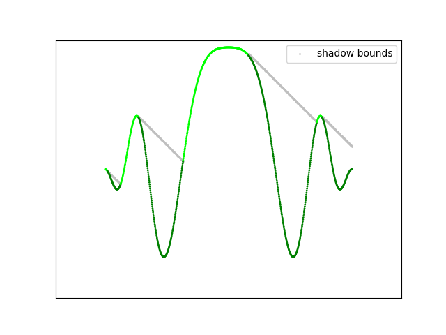
Here's how it looks animated - the build-up of the number of lines at the start is done for effect (as is the fade-out at the end).

You can check out the log entries for explanations of:

If I've forgotten anything, or you have any questions, please ask.  I had a blast programming this, and found the badge to be a lot of fun.  What I would have given to have this thing in the 1980s!

cos_table.h

pre-computed table for cosine function. Place in src directory with user_program.c

x-chdr - 7.88 kB - 11/09/2018 at 03:02

Download

user_program.c

Replaces stock badge firmware file to provide animated surface plotting demo

x-csrc - 5.48 kB - 11/09/2018 at 03:01

Download

  • Source

    Ted Yapo11/09/2018 at 03:07 0 comments

    Once you see the source, you'll understand why I felt the need to explain the algorithm.  My favorite line in the code is:

        // kill time for early frames which draw too fast
        wait_ms(4*(MAX_LINES - n_lines));
    

    When I was initially writing the code, I wasn't thinking animation at all - I figured it would be at least a few seconds to draw one image.  As it turned out, I had to add delays to the code to get it the way I wanted.  On a badge.  Crazy!

    Here's the full source code. Download Here and place in the src directory.  It replaces "user_program.c" in the project - all the other functionality of the badge remains the same, and you access the demo through menu item 7 "User Program".

    /************************************
     * This is the framework for those
     * who wish to write their own C
     * code for the basic badge
     * 
     * Take a look at user_program_temp.c (not included in project, but
     * available in src directory) to see how to use IIC routines
     ************************************/
    
    
    #include "badge_user.h"
    
    void user_program_init(void)
    {
      /* This will run when User Program is first selected form the menu */
    
      clr_buffer();
      enable_display_scanning(0); //Shut off auto-scanning of character buffer
      tft_fill_area(0,0,320,240,0); 
    }
    
    void surface(void);
    
    uint8_t first_frame = 1;
    int16_t n_lines;
    
    void user_program_loop(void){
      n_lines = 1;
      surface();
    }
    
    #include "cos_table.h"
    int16_t cos_lookup(int32_t x){
      //return 4096.*cos(6.2831853*x/4096.);
      if (x < 0) {
        x = -x;
      }
      x = x & (((uint16_t)4 << cos_k) - 1);
      if (x > ((uint16_t)2 << cos_k)){
        x = ((uint16_t)4 << cos_k) - x ;
      }
      if (x > ((uint16_t)1 << cos_k)){
        x = ((uint16_t)2 << cos_k) - x;
        return -cos_table[x];
      } else {
        if (x == ((uint16_t)1 << cos_k)){
          return 0;
        }
        return cos_table[x];
      }
    }
    
    #define S 12
    #define FP(x) ((int16_t)((x) * (1<<S)))
    
    #define ang 10.
    int16_t cs_ang = FP(0.98481); //FP(cos(ang*3.141592653/180.));
    int16_t sn_ang = FP(0.17365); //FP(sin(ang*3.141592653/180.));
    
    
    #define MAX_SURFACE_FRAMES 114
    #define MAX_LINES 40
    
    void surface(void){
      // buffer for storing pixel locations of previous frame (to erase)
      int8_t old_lines[MAX_LINES * 320];
    
      // time
      int16_t t = FP(0);
    
      // current shadow heights for each line
      int16_t shadow_z[MAX_LINES];
      uint16_t i;
      for (i=0; i<n_lines; i++){
        shadow_z[i] = -32768;
      }
    
      // controls shadow angle
      int16_t dz = FP(-0.001);
    
      // previous column's z-value used to estimate Nx for lighting calcuations
      int16_t old_z[MAX_LINES];
    
      // x step per columns
      int16_t dx = FP(1./320.);
    
      // time step
      int16_t dt = FP(0.05);
    
      uint32_t frames = 0;
      while (frames++ < MAX_SURFACE_FRAMES){
        t += dt;
    
        // increase number of lines drawn at beginning for effect
        if (n_lines < MAX_LINES) n_lines++;
    
        // kill time for early frames which draw too fast
        wait_ms(4*(MAX_LINES - n_lines));
    
        // the single unavoidable division - only one per frame :-)
        int16_t dy = (((int32_t)1<<(S+10))/n_lines)>>10;
    
        int16_t x = FP(-0.5) - dx;
        uint16_t col;
        for (col=0; col<320; col++){
          x += dx;
    
          // erase pixels in this column from old frame
          if (!first_frame){
            uint16_t i;
            for (i=0; i<n_lines; i++){
              tft_fill_area(col, old_lines[320*i+col], 1, 1, 0);
            }
          }
    
          int16_t y = FP(-0.5) - dy;
    
          // initialize hidden-line bounds
          int16_t min_row = 240;
          int16_t max_row = -1;
    
          uint16_t i;
          for (i=0; i<n_lines; i++){
            y += dy;
    
            // function to plot
            int16_t r, z;
            if (frames < 40){
              // first function: radial ripples
              r = ((int32_t)x*x + (int32_t)y*y)>>S;
              z = ((int32_t)cos_lookup(7*r-t) * ((FP(3)-12*r)))>>(S+4);
            } else if (frames < 104){
              // interpolate between first and second function 
              r = ((int32_t)x*x + (int32_t)y*y)>>S;
              z = (((int32_t)cos_lookup(3*x+y+t) * cos_lookup(2*y+x+2*t))>>S);
              z = ((int32_t)z * cos_lookup(r))>>(S+3); 
              int16_t z2;
              z2 = ((int32_t)cos_lookup(7*r-t) * ((FP(3)-12*r)))>>(S+4);
              int16_t l = (frames - 40)<<(S-6);
              z = (((int32_t)z*l)>>S) + (((int32_t)z2*(FP(1.) - l))>>S);
            } else {
              // second function : waves...
    Read more »

  • Shadows

    Ted Yapo11/08/2018 at 20:47 2 comments

    The last little trick added to the surface is self-shadowing.  At first, this seems like a very complex problem - how can you tell where the shadows are cast in the complex and arbitrary geometry of the animated functions?  As it turns out, pretty easily.

    The trick again is in the choice of the light source.  Since we have placed the light source infinitely to the left of the image, the shadows are only cast along the x-direction, in other words, the lines can only shadow themselves.  As we draw each line, we don't have to worry about shadows from any others.  The mechanism for determining if a point is in shadow or not is illustrated in the diagram above.  We start drawing the line from the left side (closest to the light source), and maintain a variable (shadow_z) representing the height of any current shadow.  As we move along the surface, if a point on the line is below shadow_z, it lies in shadow and is colored darker.  Points above the shadow_z level are illuminated, and are colored brighter (using the output of the illumination model).  These illuminated points may cast shadows on subsequent points, so shadow_z is always updated to their level.  Finally, as we traverse the line, shadow_z is decremented a little at each point to simulate the angle from the light source.

    But wait, you say: the light source is supposed to be infinitely to the left, so shadows should be cast horizontally, like on a mid-winter afternoon.  This is true, but it doesn't look as good as shadows with a partly vertical angle.  It turns out that your brain doesn't really object to the fact that the illumination and shadow models are using two different light sources.  Another cheat!

    Next Up

    Source code for everyone!

  • Lighting Model

    Ted Yapo11/08/2018 at 14:08 0 comments

    Around 1988, I added a simple lighting model to this algorithm (and later added shadows, described in the next log).  My roommate at the time had a Mac II, which was the first machine I ever used with 24-bit color.  I have photographs somewhere of the images I was able to make - some of them took hours to draw a single frame.

    The main idea is to cheat as much as possible.  The above diagram shows the vectors involved in the classic Phong illumination model.  At each patch on the surface, there is the normal vector (N), which is perpendicular to the surface at that point.  A light vector (L) points toward the light source, while a view vector (V) points toward the viewpoint.  Finally, if you want to add specular highlights, you need to calculate the reflected light vector (R).

    In this model, you have three illumination terms:

    • Ambient - this represents light from the surrounding environment which illuminates all surfaces equally.
    • Diffuse - this represents the Lambertian reflection from rough surfaces.  Think of a tennis ball.
    • Specular - this represents the highlights (direct reflections of the light source).  Think of the white glint on an apple.

    For reasons detailed below, I use only the ambient and diffuse terms.

    Ambient Term

    This term is easy.  Each pixel calculated gets a base level of intensity multiplied by its color - if the ambient illumination level is 0.25, for example, a green object with RGB color (0, 1, 0) would end up with an ambient contribution of (0, 0.25, 0) to its final color value.

    Diffuse Term

    This term is calculated using the dot product of L and N, the light vector and the surface normal.  Mathematically, this looks like:

    where N and L are both normalized to unit length.  Vector normalization is relatively expensive on the badge, requiring a square root and a division.  To avoid this, I use a directional light source parallel to the x-axis.  This is essentially a source infinitely far to the left of the image, so the light vectors are always the same, with Lx = 1, Ly = 0 and Lz = 0.  Now, two of the terms in the diffuse expression drop out, and we're left with:

    this saves two multiplications, but more importantly, it means that the diffuse illumination is simply proportional to the x-component of the normal.  Now, we can skip vector normalization entirely, avoiding the expensive square root and division.

    An added bonus is that we only need a value proportional to the x-component of the surface normal.  This can be easily estimated by a finite difference approximation using the z-value of the current point and previous point on the line:

    So, to calculate this, we only need to save the z-values of the points drawn in the previous column of the image.  Instead of nine multiplications, two square roots, and two divisions for a point light source, we can use just a subtraction if we choose the directional light source correctly.  In practice, this light source placement gives adequate visual cues to convince the brain that there's light shining on the surface.

    Once you have the diffuse term, you just multiply it by the object color as was done for the ambient.

    Specular Term

    To calculate the specular term, you first need to reflect the light vector from the surface.  This requires knowledge of all three components of the normal vector.  Additionally, you have to normalize the view vector, the surface normal, and the relfected vector, then compute the dot product, and finally raise the result to an exponent related to the shininess of the surface.  Overall, it's a pretty expensive operation for a very...

    Read more »

  • Hidden Surface Elimination

    Ted Yapo11/07/2018 at 21:10 2 comments

    This is a technique straight out of the 1980s.  I read about it in BYTE Magazine, and remember writing quick versions of it in BASIC whenever I was bored somewhere there was a computer - like in a store or during a college physics lab.

    EDIT: I found it! Read the original article here: BYTE Magazine, Vol 03, No 05, May 1978, pp.50-58. I love the freakin' Interwebs.

    I created this example in python using matplotlib to illustrate the method.  Lines are drawn parallel to the x-axis from front to back, and the screen y-coordinate is calculated from the surface height and the surface's y-parameter using a simple orthographic projection (described below). For each column, a minimum and maximum drawn y-value is stored.  This represents the bounds of the previously drawn surface.  Any parts of new lines which fall within these bounds are hidden (i.e. behind the surface already drawn) and are discarded.  When new points are drawn, the minimum and maximum values are updated.  Note that the terms minimum and maximum here refer to pixel coordinates, so the y value increases as you move down on the figure.

    This method also identifies the top and bottom sides of the surface - points drawn below the maximum y-value are on the underside of the surface (colored magenta), while points drawn above the minimum y-value are on the top side of the surface (colored green).

    Although drawing the whole line at a time works well for illustrating the method, the badge code draws the image left-to right, calculating all the pixels in the first column before moving on to the second, etc.  This has several benefits - first, during animations, complete columns of the new frame quickly replace those of the previous one, reducing annoying visual tearing.  Second, by storing the previous locations that were plotted at each column, only those pixels previously drawn on a column need to be cleared.  This eliminates the need to clear 240 pixels when only perhaps 30 have been drawn.  More about this in a future log.

    Orthographic Projection

    The projection from 3D (x, y, z) to 2D (col, row) is a simple orthographic view.  This kind of projection doesn't show perspective, but is dead-simple to generate.  This is illustrated in the following figure:

    Here, three lines on the surface are shown in 3-space (gray lines).  The x-y surface has been tilted by rotating around the x-axis slightly.  The resulting points are then projected onto the screen by simply dropping the 3D y-coordinate and using the rotated z-coordinate as the vertical pixel coordinate (what we think of as the y- or row coordinate).  It may be easier to visualize in this view:

    From the side, you can see how the 3D surface has been tilted slightly towards the screen, and the projection is simply along lines parallel to the 3D y-axis.

    In a previous log, I showed the code for setting the projection angle:

    #define ang 10.
    int16_t cs_ang = FP(0.98481); //FP(cos(ang*3.141592653/180.));
    int16_t sn_ang = FP(0.17365); //FP(sin(ang*3.141592653/180.));
    

    The values for sin() and cos() of the 10-degree angle were pre-calculated and pasted into the C-code.  These values are then used to project the y- and z-coordinate values of surface points into rows of the badge display:

    uint16_t row = 120 - (((((int32_t)y * sn_ang)>>S)+
                           (((int32_t)z * cs_ang)>>S))>>3);
     

    The constant 120 centers the surface on the 240-pixel high screen, and the value is negated because the screen row coordinates increase as you move down (opposite from mathematical coordinate convention).  This equation simply tilts the 3D x-y plane as shown in the diagrams above.  The divide-by-8 (>>3) just scales the function to fit the display properly.

  • Fixed Point Arithmetic

    Ted Yapo11/07/2018 at 14:14 0 comments

    Since there's no floating point unit on the badge's PIC32 processor, I used 16-bit fixed-point arithmetic throughout for speed.  On this 32-bit CPU, it was tempting to use 32-bit fixed point numbers, but I read in the datasheet that the MIPS 4k core could only issue a 32x32 multiply every other cycle, while it could do a 32x16 multiply every cycle.  Since you have to cast up to 32-bits to multiply two 16-bit values, I decided to stick with 16 in the hopes that the compiler would be smart enough to use 32x16 multiplies.  I haven't checked the assembly output, so for all I know, it could be doing the slower 32x32 multiplies anyway - maybe it can go even faster :-)

    Fixed Point

    I used 12 fractional bits in the 16-bit values, so you can represent values from -8 to +8, with one LSB equal to 1/4096 ( ~0.000244).  A simple macro allows you to convert floating point constants:

    #define S 12
    #define FP(x) ((int16_t)((x) * (1<<S)))

     Now, you can do stuff like this:

    #define ang 10.
    int16_t cs_ang = FP(0.98481); //FP(cos(ang*3.141592653/180.));
    int16_t sn_ang = FP(0.17365); //FP(sin(ang*3.141592653/180.));

    to set constants - here, setting the sine and cosine of the orthographic projection angle.

    Multiplication

    There are a few tricks to using these fixed-point values.  Since each value is scaled by 4096 (shifted left 12 bits), when you multiply two fixed-point values, you end up with a result scaled twice, and have to shift back by 12 bits.  For example, calculating c = a* b looks like this:

    int16_t a, b, c;
    a = FP(3.141596);
    b = FP(0.1);
    c = ((int32_t)a * b)>>S;

    Like I said above, I hope the compiler would recognize that it can use a 32x16 multiply here but I don't know if it does.  After the multiply, you divide by 4096 to remove the "extra" scaling factor.  This could all be encapsulated in some nice C++ classes with overloaded operators and whatnot, and for all I know it has already been done somewhere (probably a million times), but it was easy enough to do it the long way.  I guess even a multiply macro could help hide this.

    Division

    I tried to avoid division in the demo (even though there's a hardware divider) just out of habit, I suppose.  It's used in one place it was really needed, but otherwise, I usually used division by power-of-2 constants which can easily (and efficiently) be done with a simple right shift.

    With fixed-point math, division has the opposite problem as multiplication - after the division, you've essentially removed both scaling constants (you can think of them as cancelling), so you have to shift left to re-scale the result of the division.  This has to be done in the correct order so that the wanted bits are always on the left of the LSB to avoid losing them.  As an example, c = a/b looks like this:

    int16_t a, b, c;
    c = ((int32_t)a<<S) / b;

    I didn't research the speed of division on this processor very thoroughly.  Maybe I am avoiding it without good reason.

    Gotchas

    Having a dynamic range of (-8, +8) is pretty limiting.  Obviously, the results of any calculations need to fall in this range, but you also have to make sure that any intermediate values you calculate stay within this range too.  Sometimes just a simple re-ordering of operations will help - for example calculating the average of a and b could be done with:

    int16_t a, b, avg;
    avg = (a + b) >> 1;

     but depending on the values, the sum could overflow.  Instead, you could use:

    int16_t a, b, avg;
    avg = (a>>1) + (b>>1);

    In some cases, this may be less accurate, but will avoid the overflow issue.

    Cosine Table

    I used a 1024-element lookup table for the cosine function.  The table represents a single quadrant of the unit circle - exploiting symmetry - so there are an equivalent 4096 points in a circle . Values outside the first quadrant are folded back into the quadrant...

    Read more »

View all 5 project logs

Enjoy this project?

Share

Discussions

Morning.Star wrote 11/09/2018 at 16:01 point

Really nice drawing functions dude, very impressive :-)

  Are you sure? yes | no

EK wrote 11/08/2018 at 15:02 point

This was such a cool badge hack to see!!! Thank you for documenting it so we can learn all about how it works!

  Are you sure? yes | no

QuantumStar wrote 11/07/2018 at 20:07 point

I really enjoyed reading this, and I'm glad you included the part about using 16 bit vs 32 bit, that's interesting. Thanks for posting this :)

  Are you sure? yes | no

Ted Yapo wrote 11/07/2018 at 21:41 point

Well, once I put the code up on github, you'll understand why I feel the need to explain it - what a mess :-)

  Are you sure? yes | no

Similar Projects

Does this project spark your interest?

Become a member to follow this project and never miss any updates