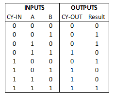
As a reminder, the ADD function has to produce two output signals according to the following table:
The next diagram illustrates how the CY_OUT signal is generated:
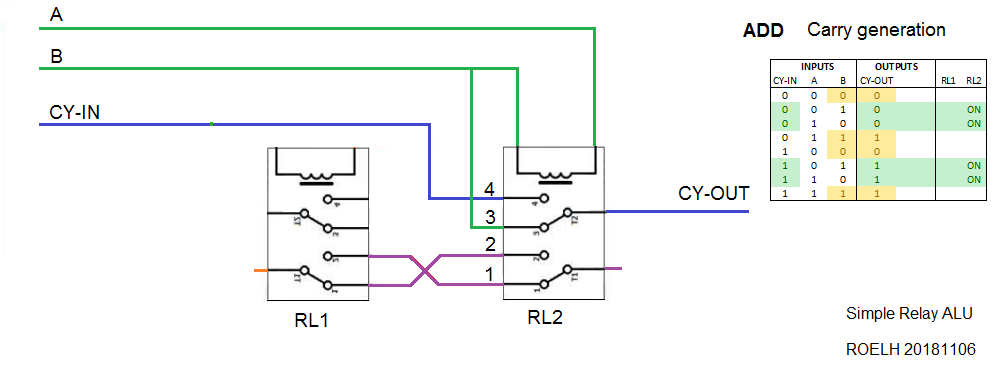
Only relay RL2 is involved for CY-OUT generation. RL2 is activated when the signals A and B are different (indicated in green in the function table).
When RL2 is activated, the Carry-output is the same as the Carry-input.
When RL2 is not activated, the Carry-output is the same as input B (indicated in yellow in the function table). It could also be connected to the A input, since A and B are equal when RL2 is not activated.
For the result output, I use two pictures, one for [Carry-in = 0] and one for [Carry-in = 1].
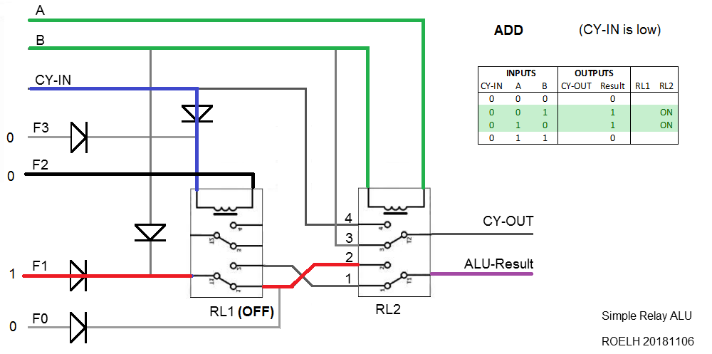
Relay RL1 is connected to the Carry-in signal, so it is not attracted when Carry-in is 0. Input F1 provides logic 1 to connection 2 of RL2. Relay RL2 attracts when A differs from B, so the result is (A xor B) according to the table.
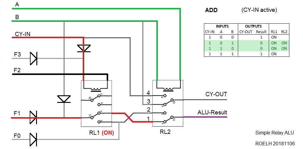
When the Carry-in is 1, RL1 is always attracted. This time, input F1 provides logic 1 to connection 1 of RL2. So the output is only logic 1 when both inputs A and B are equal.
Discussions
Become a Hackaday.io Member
Create an account to leave a comment. Already have an account? Log In.