 Ken Yap
So moving on from my 8048 adventures, I'm going to do something with my 8051 MCU chips.
For these there is an abundance of information on this family of MCUs as it's still in production but mainly as derivatives in many variants. It's probably the most long-lived MCU family and is still beloved. It's not hard to see why. Intel took the lessons it learnt from the 8048 MCU family and added more useful features. One of the most prominent is the set of bit manipulation instructions that work on single bits in special function registers (SFRs) or low memory, very useful for device control. It's estimated that these contribute to about 30% improvement in code density. These MCUs can support a high level language like C making them easier to program.
In this project I'm also going to learn to use Small Device C Compiler and the I2C protocol, the latter because it's used for communication with a 16 character x 2 line LCD panel. I hope that's not too much new tech for me to bite off in one project.
I will be summarising major accomplishments in these details, but the running story will be in the logs.
Goals
The tuner itself isn't very practical. It really should be called an equal tempered 3 octave tone generator (but that's a mouthful) using the timers of the 8051. The name is from the tuning forks used to calibrate musical instruments. Tuner apps on smartphones e.g. for guitars, do far more, even tell you how much you are off and which direction to tune the string. In fact instead of requiring the human to compare the square wave output of this tuner with the instrument's sound, why not analyse the frequency of the instrument and tell the user what to do to tune it?
It really is an excuse for me to learn several things:
- The 8051 MCU architecture
- The SDCC toolchain
- The I2C serial protocol
- The LCD1602 16 char x 2 line LCD
About the last item, there are two main varieties of displays sold on the Internet, those that are driven with a parallel interface, and those driven with serial interface. In the latter case there is a piggyback board at the back of the display carrying a chip that accepts I2C/TWI input and presents the bytes to the LCD driver chip which implements the old Hitachi HD44780 controller protocol. In software the drivers are layered, the display library presents a display interface which at the lowest level sends out commands and data using the I2C protocol.
I prefer the serial displays as these use less pins than parallel displays. The extra cost of the piggyback board is only a dollar or two.
The MCU board
I got the MCU circuit working on my breadboard after some adventures, recounted in the project logs. Here is a photo taken of it driving the TM1637 display from my previous 8042 clock project which has a simpler interface and whose protocol I'm familiar with.
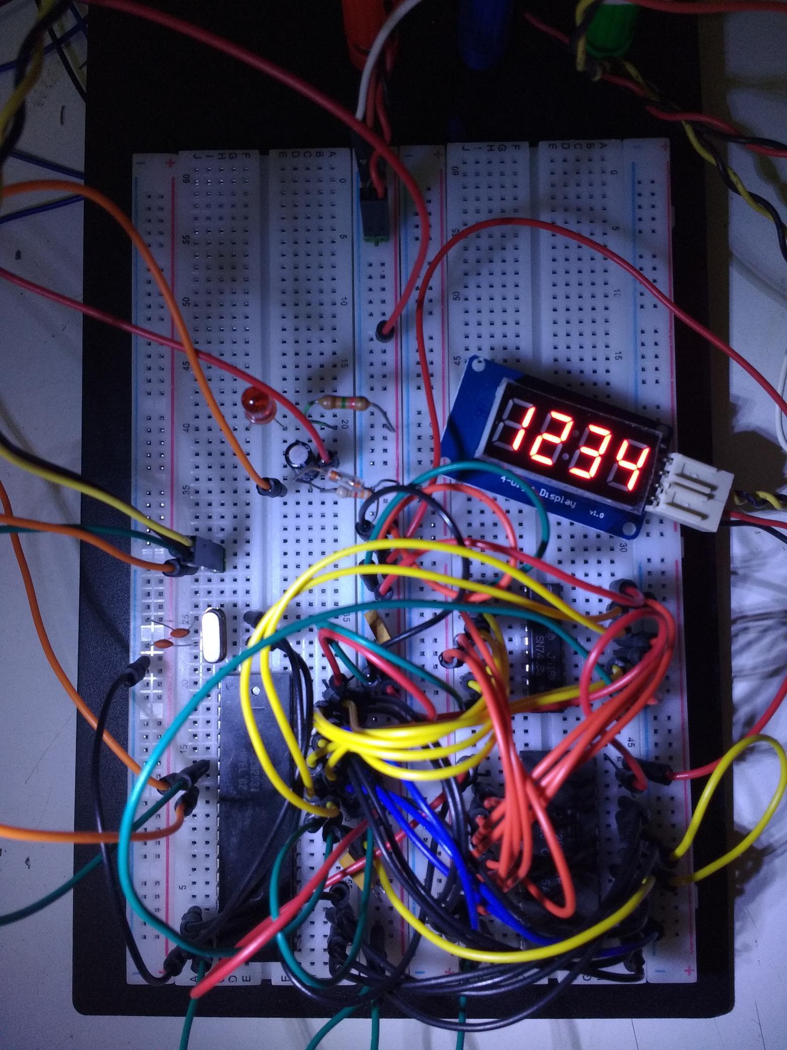
It's a bit harder to see the chips as the off-the-shelf jumper wires take up more room than the homemade ones in the last project but there is an 8031 MCU (8051 with no internal ROM), 28256 EEPROM, and 74LS373 8-bit latch, plus some small components like the crystal clock source and reset circuitry. The LED and resistor were used to get the blink program working.
Tone generator and switch handling working
The tone generator is probably the simplest part of the project. I just program timer 1 to flip the speaker port bit every half cycle. The frequency is determined by the clock divisor programmed into timer 1. The divisor table in the C code is pregenerated using a Python script.
I also got the note increment and decrement buttons working, using a Protothread handler, as described in a log entry.
What remains is the code for displaying information on the I2C 16x2 LCD display.
Display working
I have the display working. See log entries for remarks on implementation details. Here is a short video showing the display while the decrement note button is held down.
The firmware has been published to Github. Now I can dismantle the circuit and use the breadboard for the next project!