 risknc
This will be a significant challenge due to the desired accuracy / scale of the arm.
Some Considerations
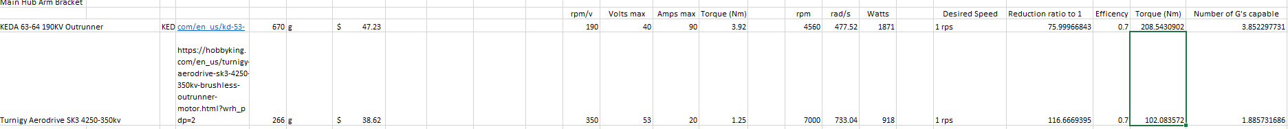
- Motor Selection - Aiming for Brushless DC for power density / low cost
- Driver Selection - Currently using Odrive, looking to implement with FOC (field oriented control) for low vibe / high torque at low speed.
- Encoder Selection - Investigating implementing 16 bit magnetic encoders w/odrive
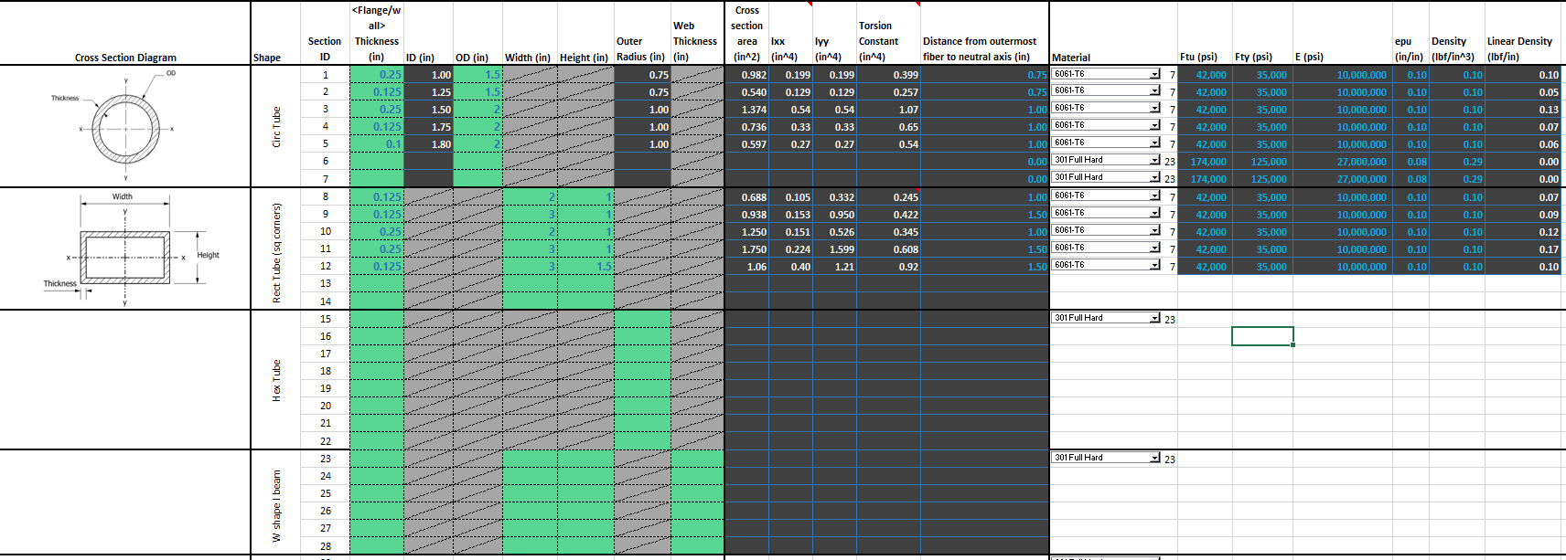
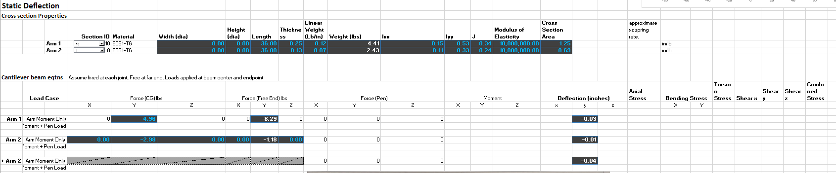
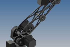
- Arm Material / Cross Section - Prototyping in Aluminium, later considering Carbon Fiber Reinforced Polymer (CFRP)
- Bearings - Considering low cost IGUS slew bearings, may have too much lash, will also look into thin section roller bearings, bushings.
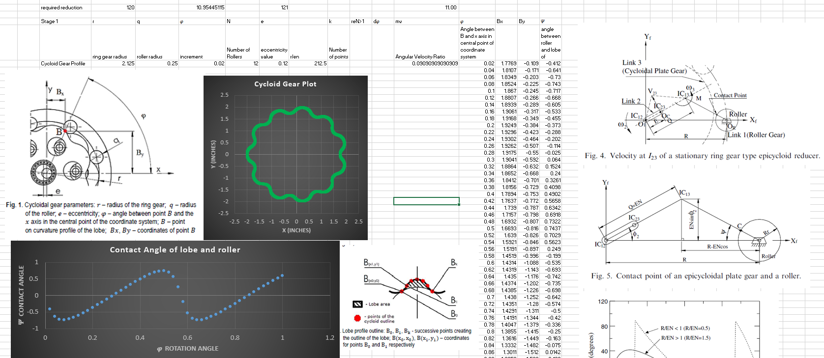
- Gear reduction - Looking at cycloidal drive for low backlash, low cost of manufacture, also considering a differential belt driven system with two input motors per axis if the lash is too high with cycloid.
 Andrew Becker
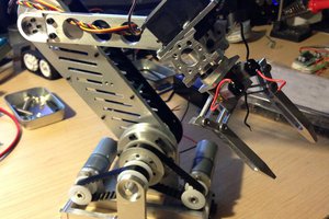
 CLo
CLo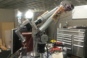
 Colin Kingsbury
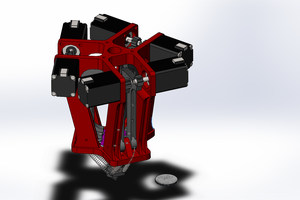
 David Brown