0%
0%
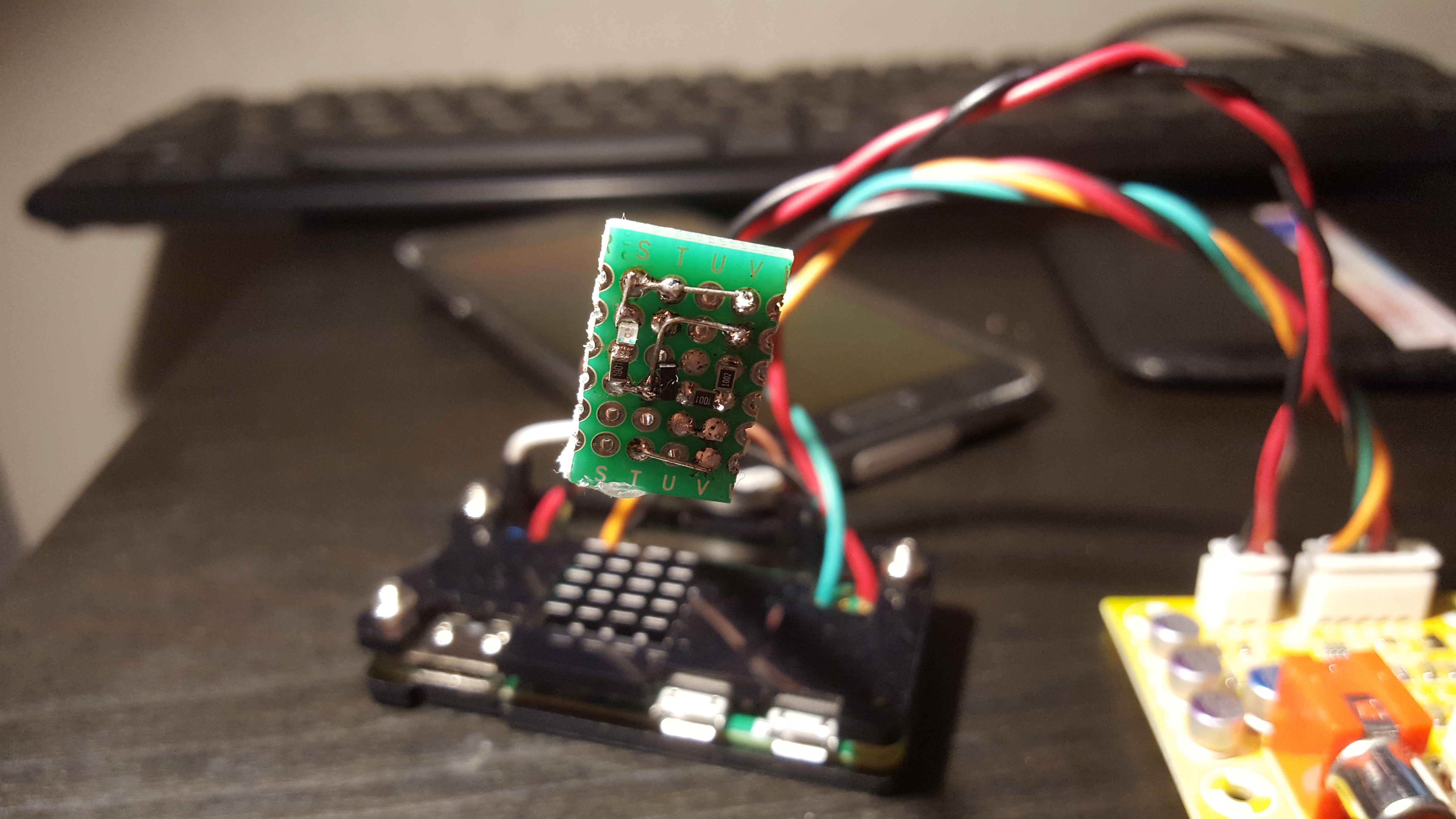
OrangePi Zero pulse music server using I2S DAC
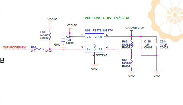
Music server based on orange pi zero v.1.5 board, PCM5102 I2S DAC, and pulse server and mopidy running in docker on the software side.
 andriy.malyshenko
Become a Hackaday.io member
Already have an account? Log in.
Just one more thing
To make the experience fit your profile, pick a username and tell us what interests you.
Pick an awesome username
hackaday.io/
Your profile's URL: hackaday.io/username. Max 25 alphanumeric characters.
Pick a few interests
Projects that share your interests
People that share your interests


 Mirko
Mirko
 C. M. Herron
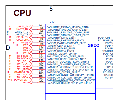
How to make install serial uart MIDI library from this sample library MIDI "rpidmx512/platform_midi.h at master · vanvught/rpidmx512 · GitHub" https://github.com/vanvught/rpidmx512/blob/master/lib-midi/src/h3/platform_midi.h