Close
0%
0%

Make a cheap bike light better!

Hardware and software improvements to a £10 LED cycle light

Public Chat
Similar projects worth following
1.8k views
0 followers
I bought a cheap 4-LED bike light with the intention of making it as bright as practically possible, without it melting itself!

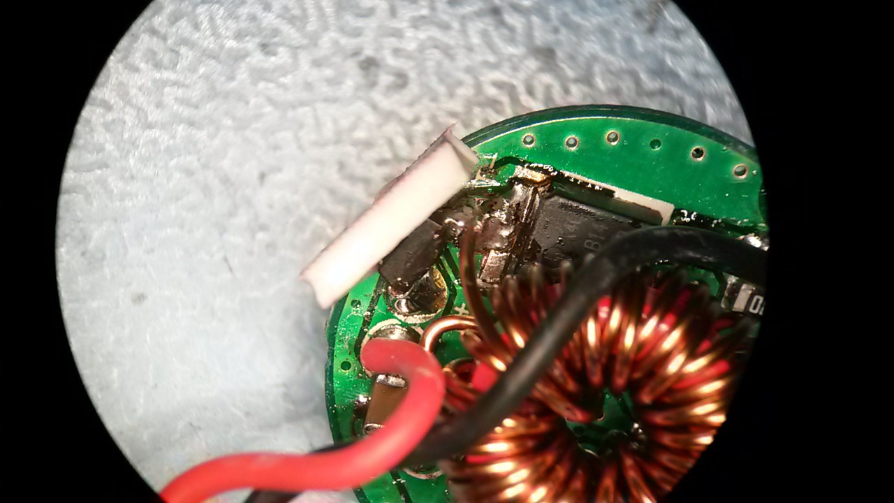
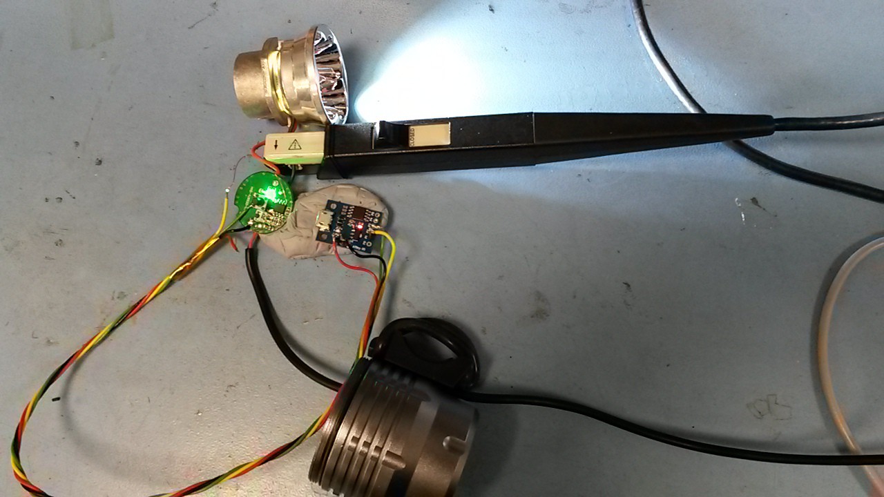
The basic light is pretty well-engineered. It has what look remarkably like four CREE XM-L T6 chips (under microscope inspection), with a good thermal bond to an aluminium back casting, plus cast alu reflector (not plastic). All that solid metal should mean good heat dissipation. The outer housing is a nice bit of machined alu too, with O-ring seals and cable glands to keep most of the rain/mud out. Not a bad donor light.

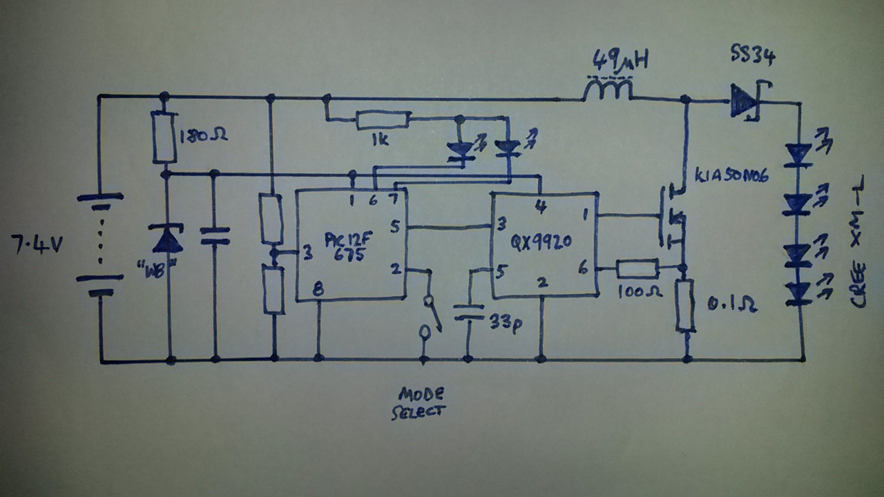
The driver board is a bit on the weak side: it's a QX9920-based boost converter, with a decent sized MOSFET for switching duties, though the main inductor looks a bit small (like it might saturate and/or get hot). As usual for these kind of lights, there's a PIC/clone which controls the lamp dimming and switches between red and green LEDs to show battery state. It has two brightness modes,  'full' and 'half'(ish), as well as a driver-annoying strobe mode.

Performance? Well, it's about as bright as my dual-LED light, which also has CREE XM-L's. This is not too surprising since both lamps draw about the same current (1.8A from 7.4V). So although the new light has 4 LEDs, they're only being driven half as hard. Plenty of scope for improvement then...

The plan is a) to mod the hardware to push a bit more current through the LEDs, and b) mod the firmware to add some more helpful dimming modes.

  • 1 × basic light 2800lm 3-Mode White Bicycle Headlamp w/ 4 x Cree XM-L T6, SKU 187987 on DX.com
  • 1 × attiny85 Microprocessors, Microcontrollers, DSPs / ARM, RISC-Based Microcontrollers

  • A year on...

    RobG10/01/2019 at 12:52 0 comments

    The light proved pretty reliable and useful during last season, and I'm just getting it prepped ready for this winter. The last couple of rides have had the occasional blackout, so it's in pieces on my bench again!

    I've swapped out the small SS34 Schottky and replaced it with a physically larger 30BQ060 that I had lying around. Hopefully the bigger package means better thermal dissipation into the case. Also I've glued the board into the casing because it looked like it might have rattled loose. Hopefully these two changes will cure it once and for all...

  • Nearly there.

    RobG11/27/2018 at 13:12 0 comments

    A bit of a breakthrough today: unless I change the whole driver to a synchronised boost design (i.e. with a MOSFET instead of a diode) I'm always going to be stuck with loss in the diode - to the tune of about 4-5% of the total power delivered to the LEDs, or about 0.5-0.75W, which will cause it to get pretty hot without heatsinking. It occurred to me that if I roll the diode chip over on its side, and move it toward the board edge slightly, I can pack the gap between it and the metal casing with a thermal gap filler. This makes a (not too terrible) thermal path to case in addition to the path through the PCB itself, so should help cool the diode.

  • Yeah, not bad.

    RobG11/26/2018 at 14:56 0 comments

    Went for a spin last week in ~4°C ambient conditions and the light worked pretty well. Actual light output is probably bright enough (though of course I want more!), and I'm pleased to report that the thermal back-off worked. After about 5 mins on full it did indeed get hot enough to trigger the Atmel to switch to 'low' mode rather than catch fire...which was nice. But disappointed that it got that hot at all.

    Have now built a model in LTSpice which indicates that reducing the switching rate should bring the MOSFET dissipation down without affecting too many other things, so I've increased Coff to 133pF (100pF added to the 33p on the board) and now it switches at ~50kHz - about a third of the original rate. Under the thermal camera things are a bit better: the MOSFET is now relatively cool, and it's the Schottky (a Vishay SS34) that gets hot first. I need to sort this before I reduce the sense resistor further to squeeze more current through the LEDs...

    I've also added a 4u7F X5R ceramic across the output terminals. This ought to make the LEDs perform better, by reducing the peak current without changing the mean. (For example, according to the XM-L datasheet, running them at 1A continuous should produce 12% more light than running 2A at 50% duty). Without a light meter I doubt I'll be able to tell the difference though.

  • Ready for first trials

    RobG11/21/2018 at 11:00 0 comments

    - wrote some more Atmel code last night to implement a thermal cut-out at about 75-80C

    - steamed the ATTiny85 off the Digispark board and dead-bugged it onto the light PCB, made connections with enamelled wire

    - all seems to work ok

    - will re-fit front glass and take it for a spin tonight, to see if I can let the magic smoke out. :)

  • Things are warming up...

    RobG11/20/2018 at 16:28 0 comments

    Took the old inductor off and measured it on an LCR bridge at about 49uH. I then wound a new one using thicker wire on a slightly larger core, again aiming for 49uH. I now realise that the inductor isn't getting warm, it's the MOSFET. Using a thermal camera I could tell that the MOSFET case was hitting 90°C and rising after about 20 secs on full power.

    I've increased COFF (by adding 39pF in parallel with the 33pF that was there) to halve the switching frequency. This means the MOSFET spends half as much time in its not-quite-off-not-quite-on state where it dissipates heat. Seems to have helped, as it's now starting to level out at about 70°C. However, the mean LED current (whilst on) is also slightly down now at about 2.25A, plus duty is 47%.

    From Cree datasheet, that puts the average light output at about 1300lm. A bit better...

  • More power, Igor!

    RobG11/20/2018 at 12:28 0 comments

    Yup, adding 1R in parallel with the 0.1R sense resistor already on the board increases the LED current to about 2.4A (average during 'on' period) peaking at about 2.6A, and the overall supply current to about 2.4-2.5A, i.e. 10% more as expected. I would go further, but I've just noticed the inductor gets quite warm. Time to source a new (bigger) one...

  • New controller

    RobG11/20/2018 at 09:01 1 comment

    Have now bodged on a Digispark board (ATTiny85) with code to control the LED modes, so I can now have a 100% mode (yay!) and any other dimming levels/flash patterns that I want. Had to run the micro at 1MHz to get the power consumption down as the puny zener-diode-based supply wasn't man enough for the 18mA the Digispark wanted. (The original PIC-clone draws about 0.6mA, for comparison). 

    The total dissipation at max brightness is now up from 1.8A to about 2.2A.

    Next step: lower the current-sense resistance to push more current through the LEDs.

  • First thoughts

    RobG11/19/2018 at 19:25 0 comments

    Reverse-engineering progress so far:

    - have worked out most of the circuit (will add diagram later)

    - design is QX9920-based, but configured in a rather odd way to make it boost rather than buck

    - as a result, the switcher only has a duty of about 50% (half the time 'charging' the inductor, the other half of the time 'discharging' it). I don't think I can change this.

    - the 'off' time of the QX9920 (LEDs are ON in this cycle) is fixed using a capacitor. The 'on' time (LEDs off, inductor charging) is controlled by low-side current feedback sense.

    - currently, the LEDs get pulsed with about 2.3A for 50% of the time, which is not much. XM-Ls are specced up to 3A (assuming they don't melt first).

    - the microcontroller runs the QX9920 at about 80% duty making the light even dimmer. I wonder if the designers had trouble keeping the LEDs cool at 100%?

    - so 2.3A at 50% x 80% duty puts the light output at about 1000 lumens total (at low-ish temperatures). Certainly not the 2300lm it was advertised with!

View all 8 project logs

Enjoy this project?

Share

Discussions

Similar Projects

Does this project spark your interest?

Become a member to follow this project and never miss any updates