 Sander van de Bor
A simple board, which can be used in wearables, using the following specifications:
- Simple attachment for APA102 LED strips;
- Integrated LIPO charger;
- Compatible with Arduino IDE;
- Easy to manufacture (with reflow oven).
Board design which makes it easy to attach LED light strips (APA102). No soldering is required by the maker who is using this board
Already have an account? Log in.
To make the experience fit your profile, pick a username and tell us what interests you.
A simple board, which can be used in wearables, using the following specifications:
Ranbow Star - Large.pdfLarge template of the star, including zipper locationAdobe Portable Document Format - 5.89 kB - 07/05/2019 at 01:13 |
|
|
Template - Rainbow Star.pdfSewing template for star (3 sizes)Adobe Portable Document Format - 6.09 kB - 01/28/2019 at 22:33 |
|
|
Template - Heart and Circle.pdfSewing template for heart or circleAdobe Portable Document Format - 6.24 kB - 01/26/2019 at 04:14 |
|
|
ATtiny_Freemover.zipKiCAD schematic and PCB designx-zip-compressed - 268.66 kB - 12/09/2018 at 03:46 |
|
|
Last year I taught about 80 kids how to make the LED wearables. The results are always a lot of fun, but the road to get there can be challenging. The netting is just very difficult to work with, and gets stuck in the sewing machine most of the time. I tried supporting it with paper, and that helped a little, but removing the paper after sewing everything together was another drama.
So for an upcoming workshop I decided to try something new. For another project I started using felt, and it was so easy to work with compared to the netting. You can use chalk to mark your cutting and sewing pattern, and it never pulls into the sewing machine.
And the results are remarkable! See some of the pictures below:
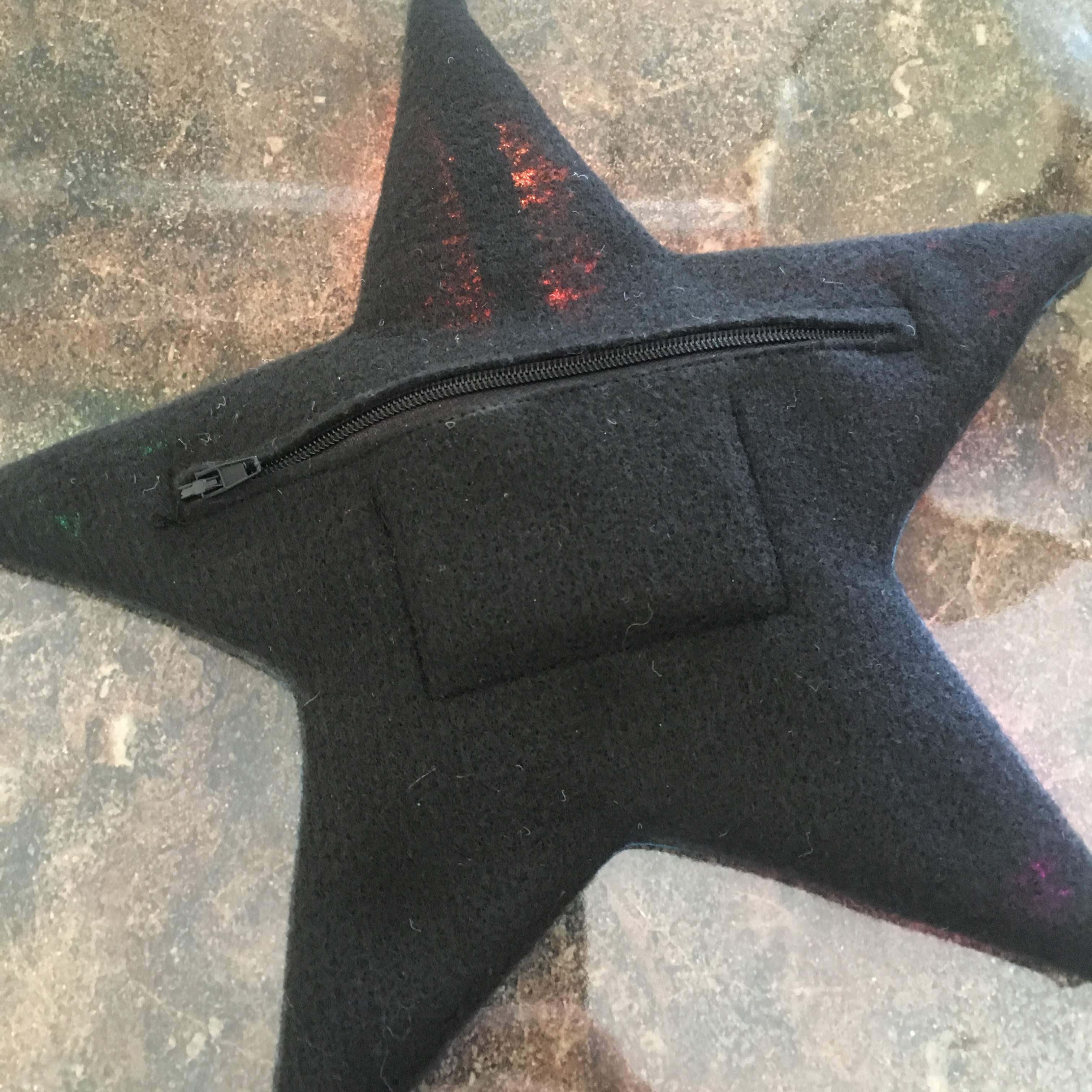
The black behind the netting gives a colored dark border seen when the wearable is turned off. The back looks very clean and the black zipper blends in:
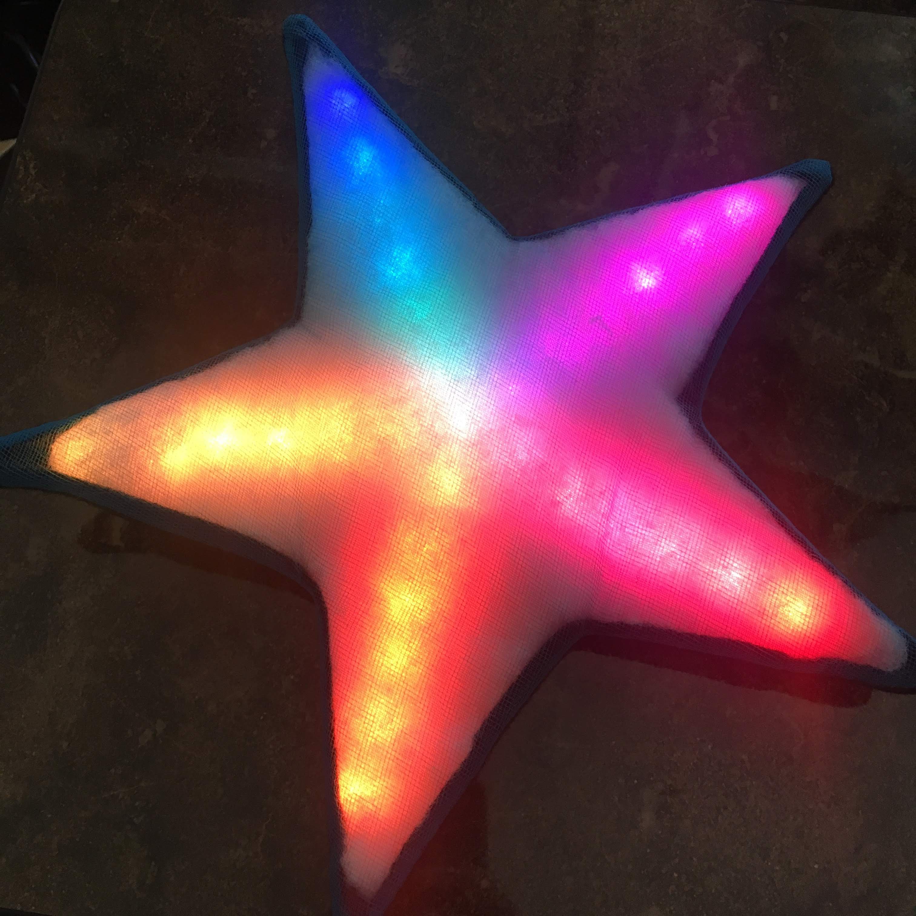
But it looks really great when it turns on. I really like the darker edges:
Hopefully this next workshop will go smooth! I will update the instructions with the feedback I will gather.
The original board, using the ATSAMD21G18A, had tons of I/O pins to work with (38 actually), and was using only 1 data line for the LED's. Adding inputs was not an issue since most pins were not used anyway.
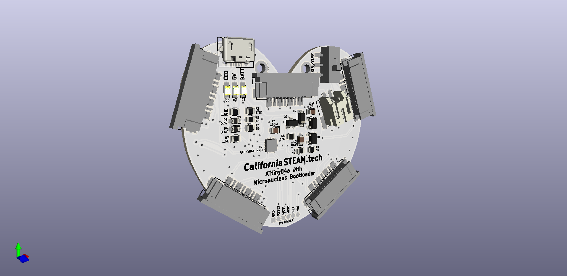
This ATtiny84a board has less I/O pins (12 only), and most of the pins are assigned already as follows:
Using 11 pins, leaving me with only 1 pin for an input, and I want 5!
I could charlieplex 3 pins to create 6 inputs, but that requires diodes and just makes it more complicated.
So in order to get to my 5 inputs I had to combine inputs with other features. The reset is used when programming the board with a SPI programmer, but with Micronucleus installed I no longer need it, so that will be my second input. The indicator light can be combined with an input, so that is the third, and I decided to use the USB lines for my last two inputs.
The USB is tricky, because it has pull-up resistor in the D- line, some Zener diodes to ground and some resistors to the USB port itself. The pull-up resistor is on pin#10. After making all pins inputs with pull-up resistors the program was acting up. It was reading an input from pin#10 constantly while plugged in on the USB. I tried setting the pin high (might burn out the pin) and that made it a little better. Fortunately it was all working fine after unplugging the USB cable, and since this is a wearable, it is no issue when the inputs are not working while plugged in.
Second problem was the use of delays in the original code. it is impossible to read the input pins while the sketch is using the delay, and this should be replaced by millis() instead. Adafruit has a great tutorial on this here.
This tutorial is using the Neopixels, but just some small changes were required to make it work with the DotStar (APA102) used on this project. The entire code can be found here on Github.
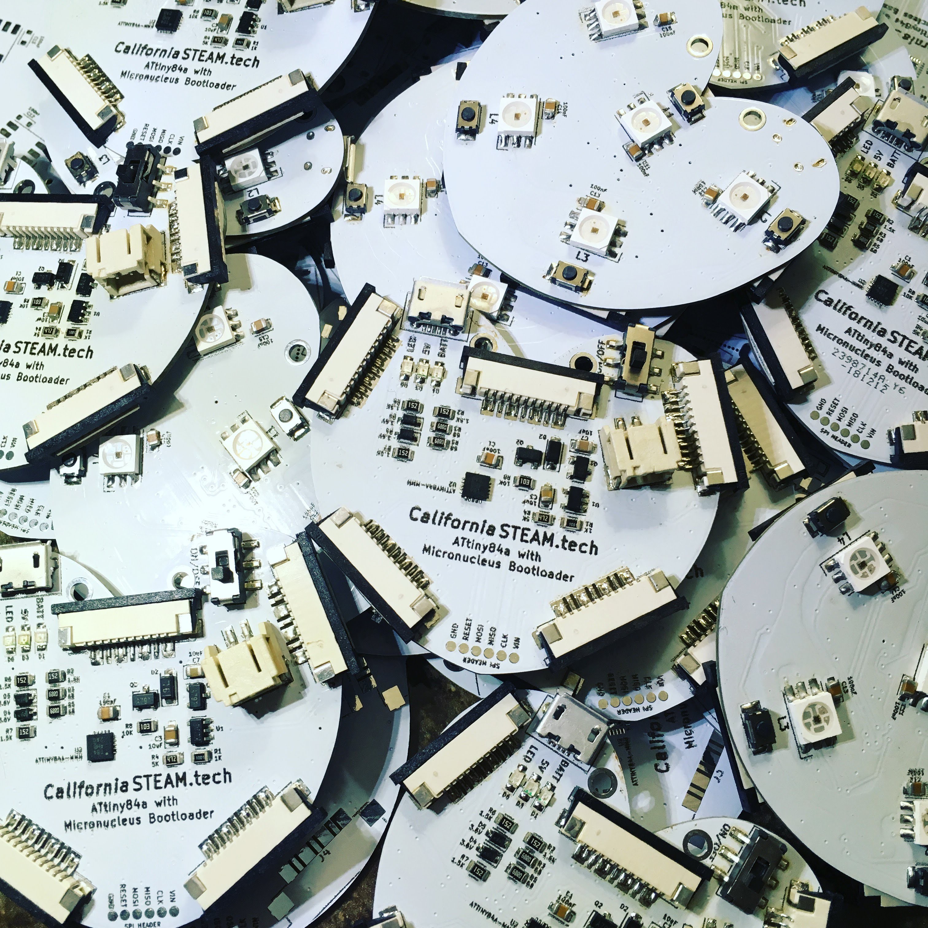
Last couple of days I have been working on the first small production run of prototype boards which I can use for upcoming classes. I will make some available on Tindie as well. Making about 16 of these took a little bit longer then anticipated due to some damaged RGB leds. The APA102 RGB's came in a sealed bag, so I decided not to bake these before use, but that was a big mistake! I could hear them popping in the reflow oven around 200°C. Fortunately I was able to recover all the boards by removing the APA102 RGB and solder the replacement by hand. I still have to finalize the Arduino board manager (create the JSON file) and check if all the push buttons are working. One of the buttons is connected to the reset pin, but with the micronucleus bootloader this pin is no longer needed and I can burn the fuse to make it a regular pin.
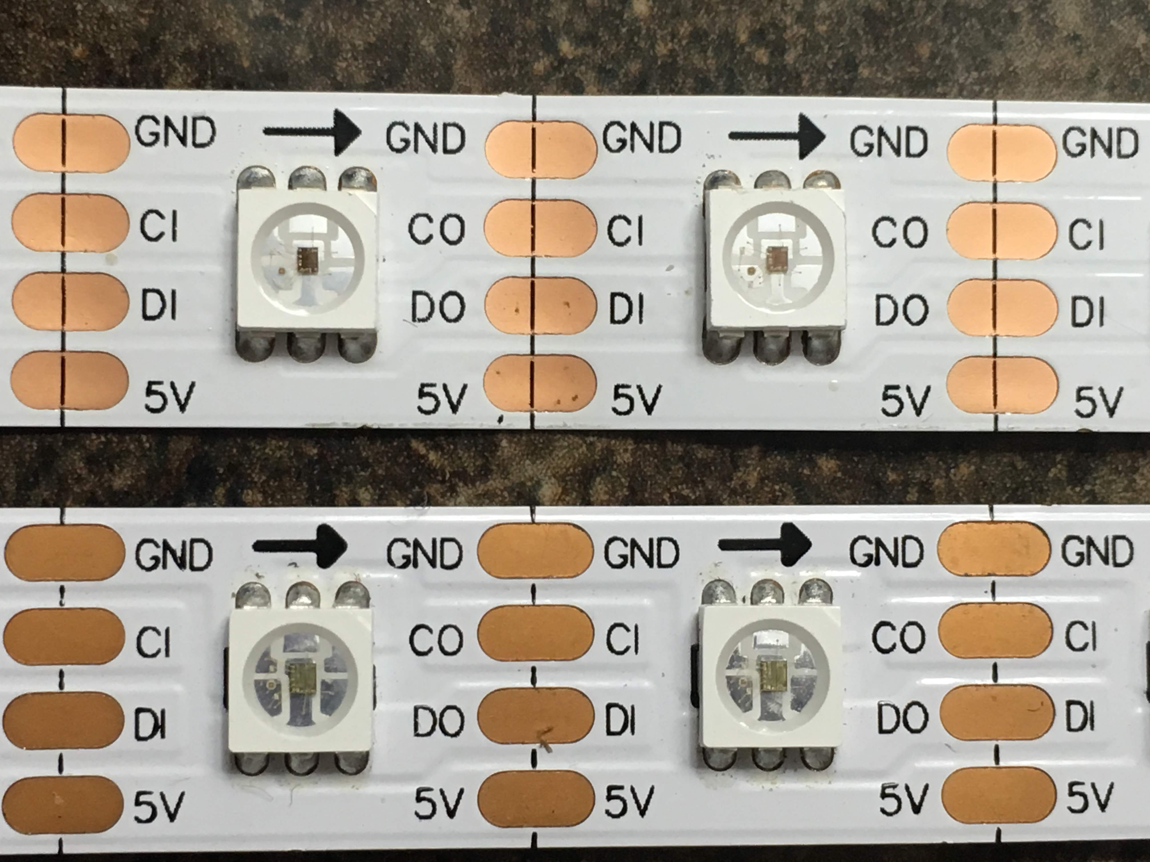
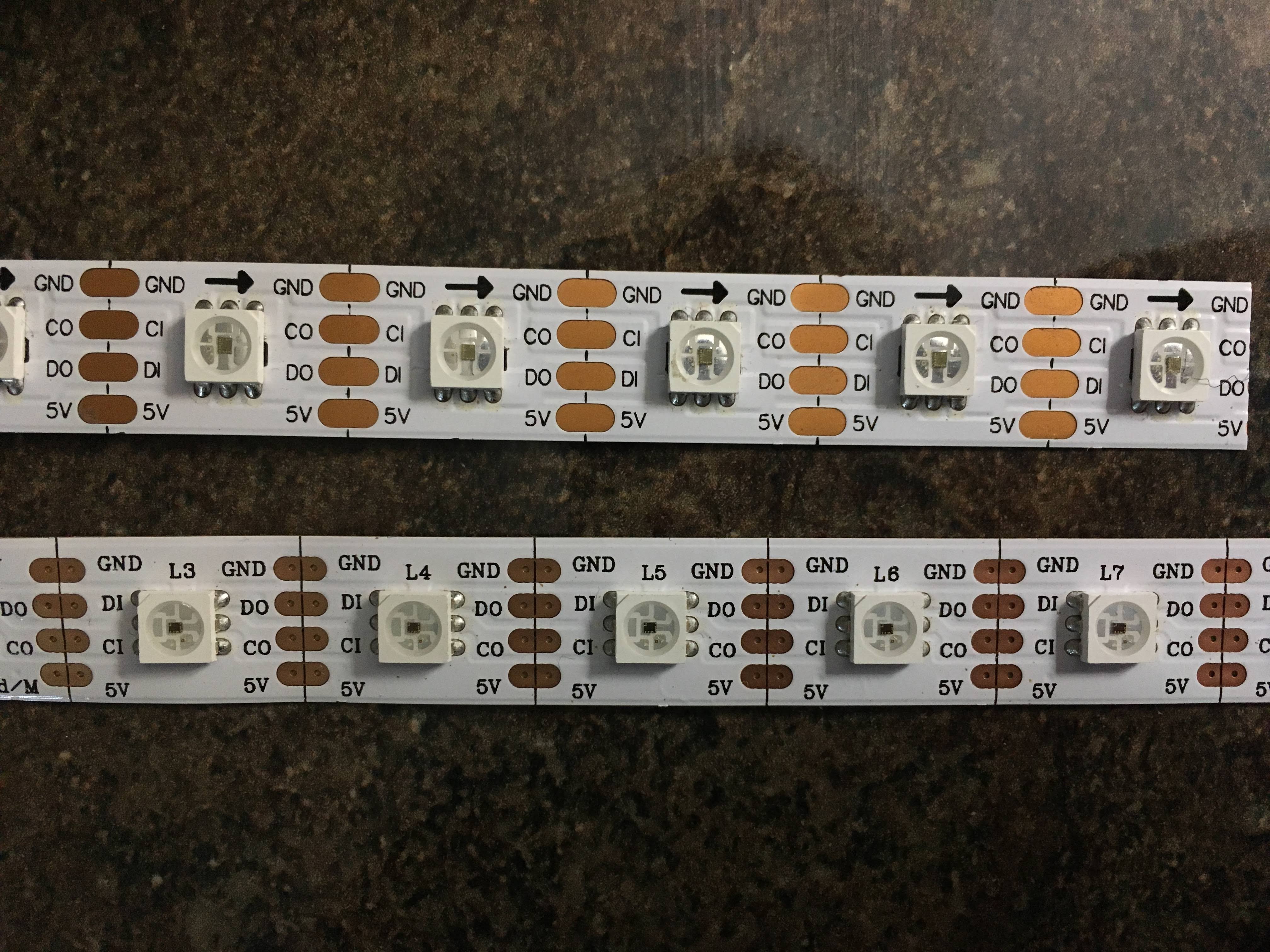
The new LED strip works great with the board. The pin-out is the same, and at a first glance the entire strip looks the same, but there are some differences:
The top show the new strip, and when you look closely, you will notice the smaller chip. These are SK9822 chips instead of APA102. Not an issue and the actual LED on the board is SK9822 already. The strips are thinner and more flexible, 0.34MM vs 0.46 of the APA102 strip. The FPC connector is recommending strips around 0.3MM, so the new strip should work better. Unfortunately I have been using the 0.46mm and this might have damaged the connector and these new strips are loose in the connector, but could be held with some super glue if needed.
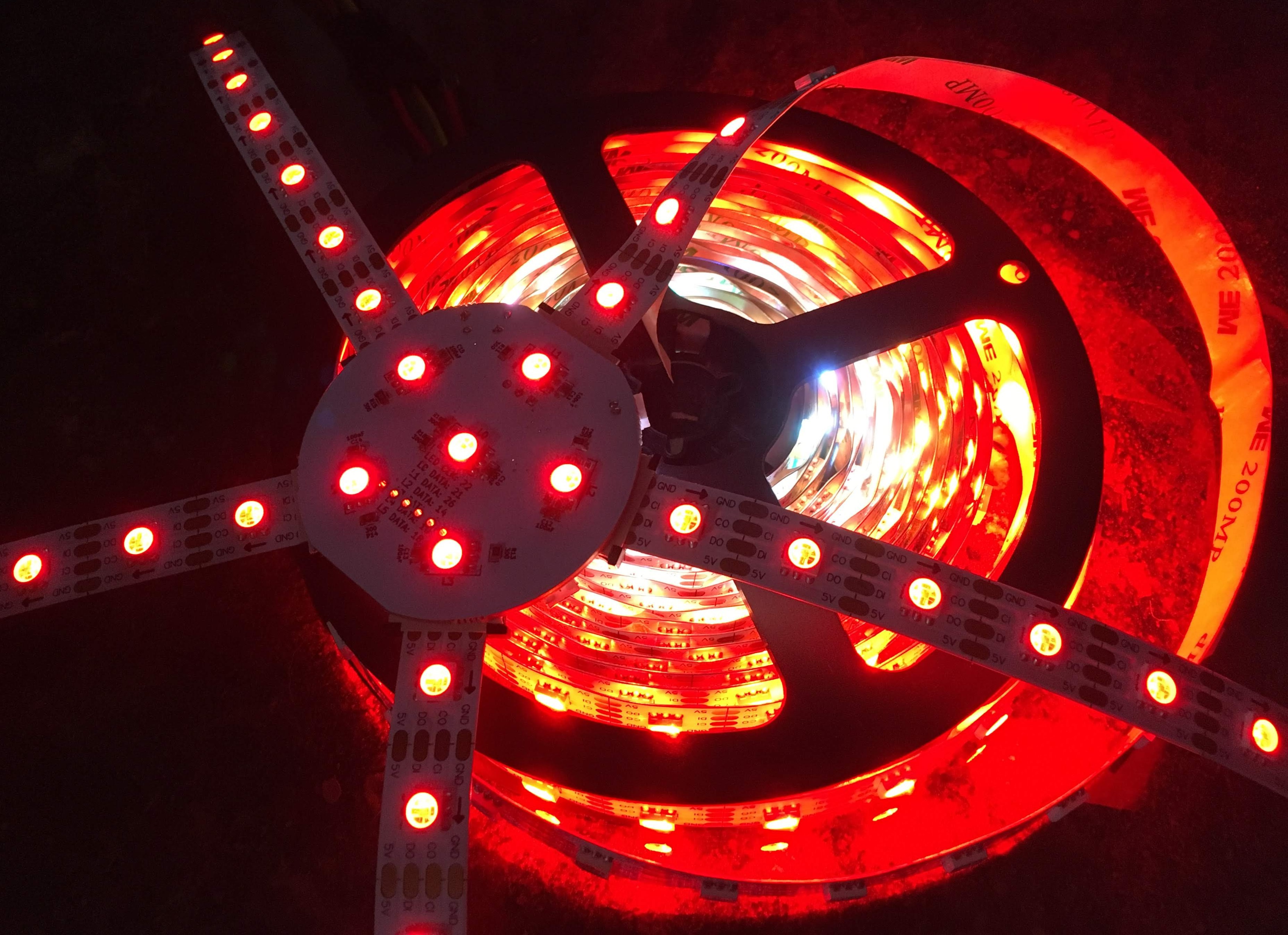
I tested the entire strips by connecting a 8A power supply to the end of the strip, and turned all the LED's to full brightness, white color:
You will notice that the inside of the strips is white (where the power source is located) but appears more red toward the end. My power source is not sufficient enough and since the RED led has the lowest voltage forwarding, it is the only LED turning on.
An LED usually requires about 20mA to be as bright as possible without causing any damage. Since the strip above is 5 meters long, with 60 RGB LED's per meter, it requires 5 meter X 60 RGB leds X 3 leds per RGB X 20mA = 18000mA, or 18A. I need a larger power supply.
In this project we are only using small sections of the strip, but keeping an eye to the power consumption is still very important. We want the wearable to last as long as possible. This can accomplished as follows:
The largest battery I use in most of my projects is 1200mAh. It is recommended to charge and discharge the battery at a rate of 2 times the capacity, so at a maximum rate of 600mAh. Most of my wearables last up to 4 hours before a recharge is required.
When I started this project, I ordered different APA102 strips to determine the pin-out. I decided to go with GND - CLOCK - DATA - GND. The strip fits perfect into a 11 pin FFC connector. Each solder pad on the strip connects to two pins on the FFC, creating a pretty reliable connection.
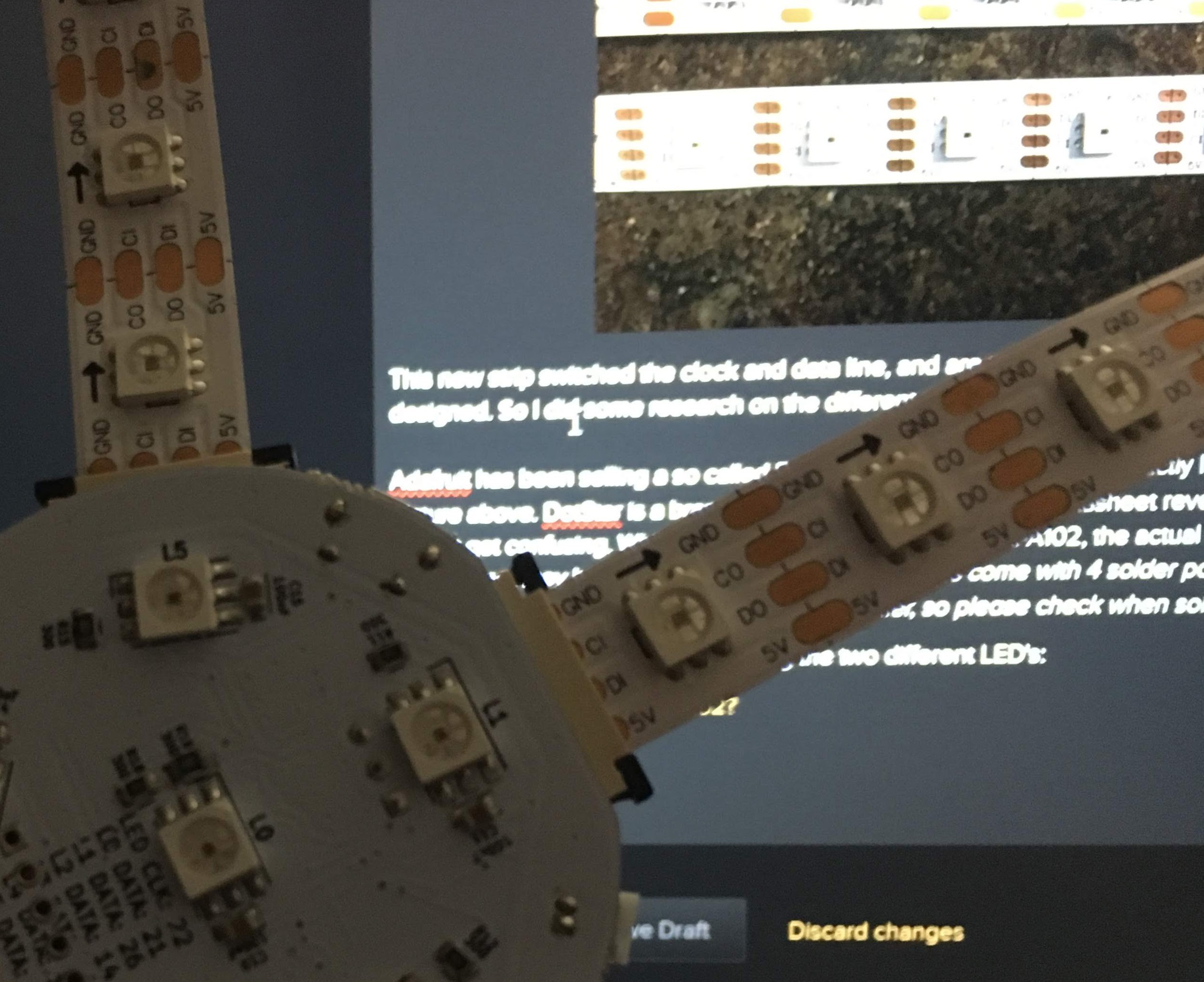
For this new board I ordered an additional strip, 5 meters, but unfortunately the pin-out is different:
This new strip switched the clock and data line, and are no longer compatible with the boards I designed. So I did some research on the different strips out there.
Adafruit has been selling a so called DotStar LED strips which looks exactly like the top strip in the picture above. DotStar is a brand name from Adafruit, and the datasheet reveals the actual type of LED. Here it gets confusing. While the technical details mention APA102, the actual datasheet is for SK9822. Even worse, they have a note with the following: Strips come with 4 solder points per segment, but the arrangement may vary depending on the supplier, so please check when soldering/powering!
So I found the following link comparing the two different LED's:
SK9822 – a clone of the APA102?
So after taking a closer look at the board and strips I have been using so far, I noticed that the LED's on the actual board are SK9822, and the strip is APA102. I have not noticed a difference in performance and they behave well together.
Last week I contacted different suppliers to confirm the pin-out of the solder pads and I am expecting a new strip at the end of this week. Fingers crossed it is compatible, and I can keep this project moving.
There are not a lot of boards out there using Micronucleus, but Digispark is one of those boards. I created a custom board within the hardware specifications of the Digispark boards were I added a ATtiny84a running at 8 MHz. Unfortunately the core kept compiling at 16 MHz, resulting in the delay being too slow and the SPI not working.
I moved on with the ATTiny Core from SpenceKonde, but there was no Micronucleus support for that, only AVRDUDE. I found a compromise where I can use the ATtiny core and the upload tool Micronucleus from Digispark. Unfortunately with Digispark installed LTO can no longer be used. Something I have to solve in the next couple of days.
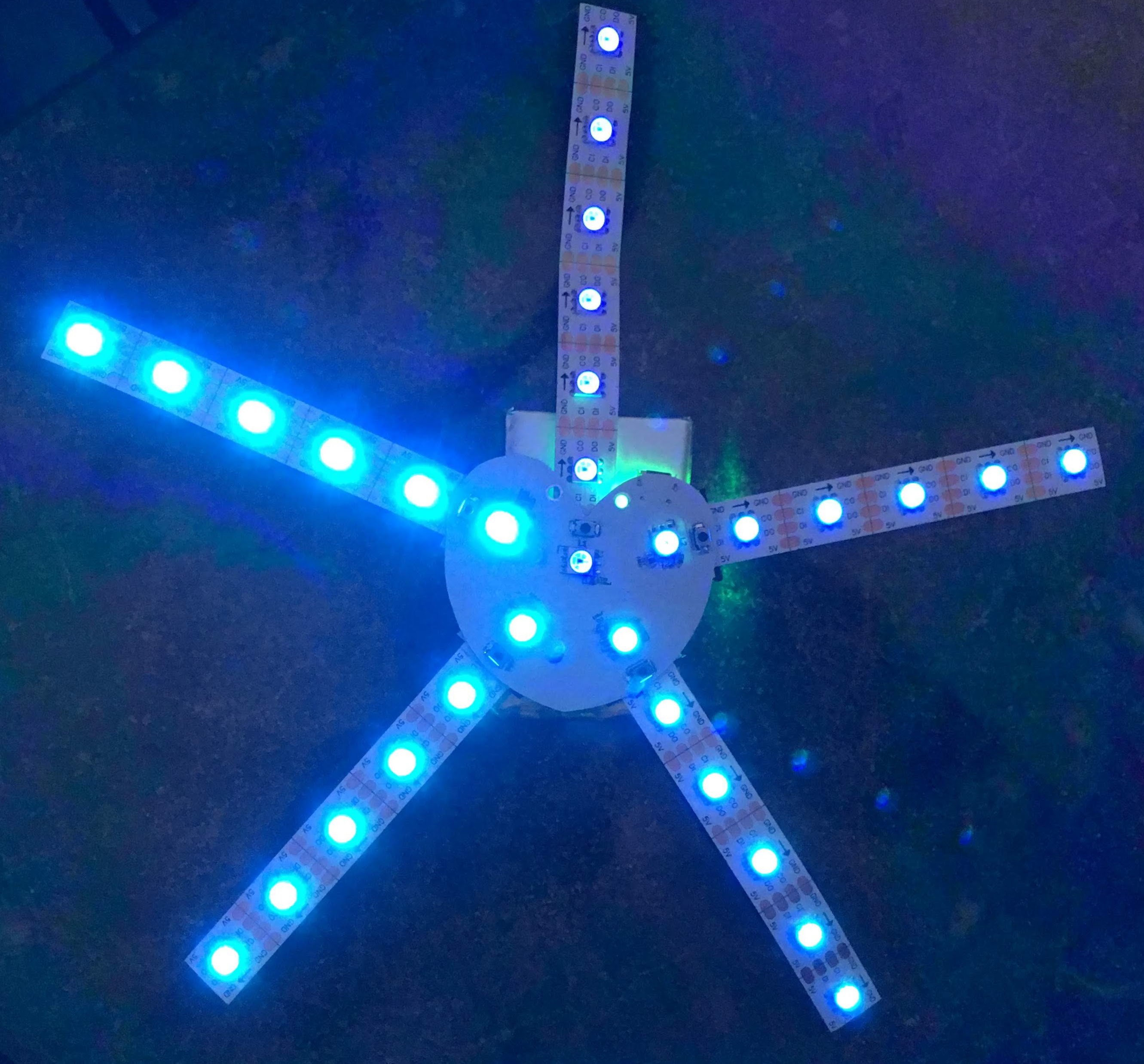
I am using the Adafruit DotStar library and made some minor changes to add the ATtiny84 to have it compiled correctly. I made a basic program where I update the LED's on each leg individually. The program uses about 65% of the flash memory (randomSeed actually took quite memory), and there should be plenty left to create some great patterns.
Here is a video of the programming and the rainbow pattern:
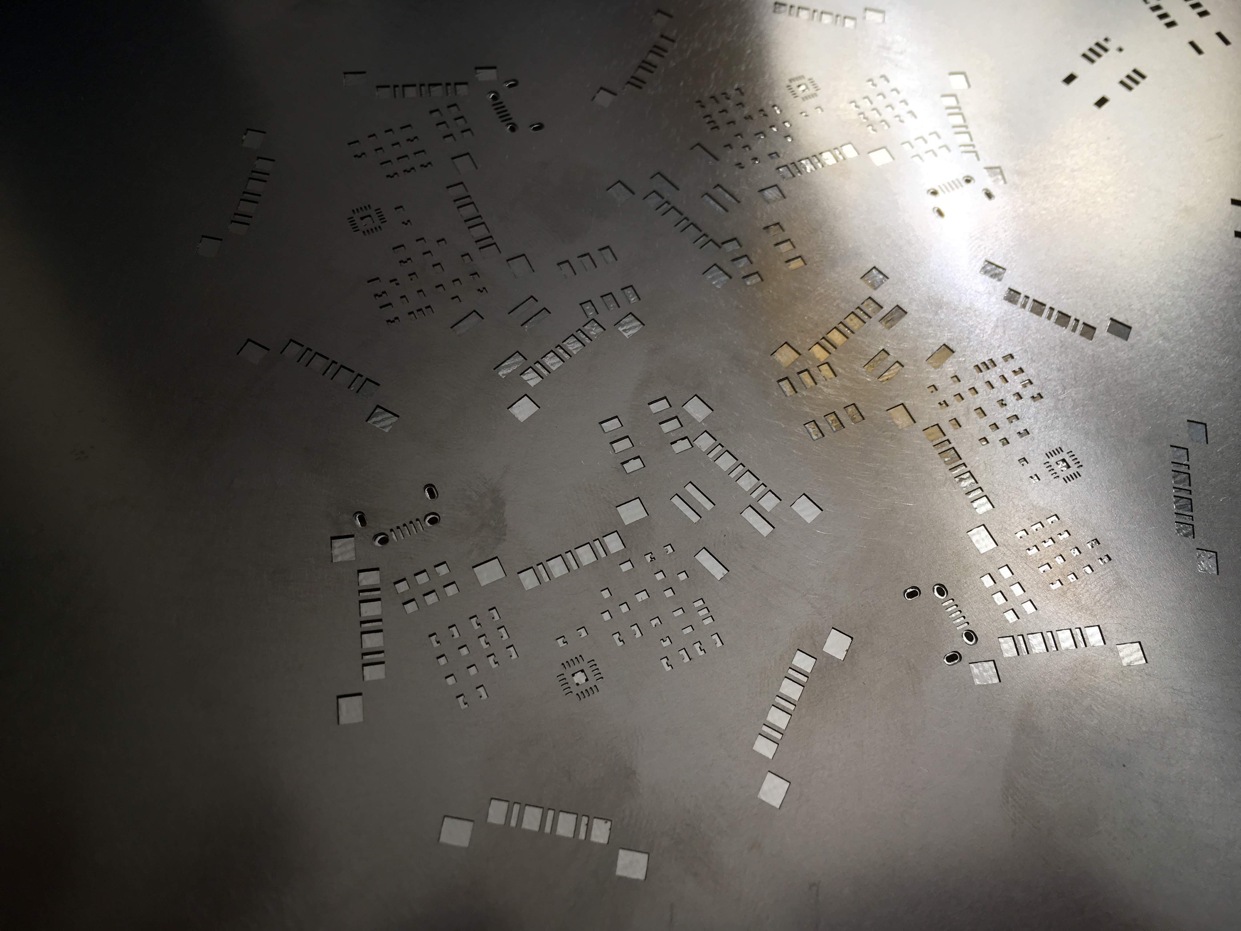
I just started my 11 day holiday vacation, allowing me to spend more time on this project. First step is manufacturing of the actual board. I noticed on the stencil that the solder pads for the USB connectors are part of the stencil as well, something I did not do on my other projects. It actually worked out great, because the solder paste that is pushed into these through holes are holding the USB connector very well, and no second operation is necessary.
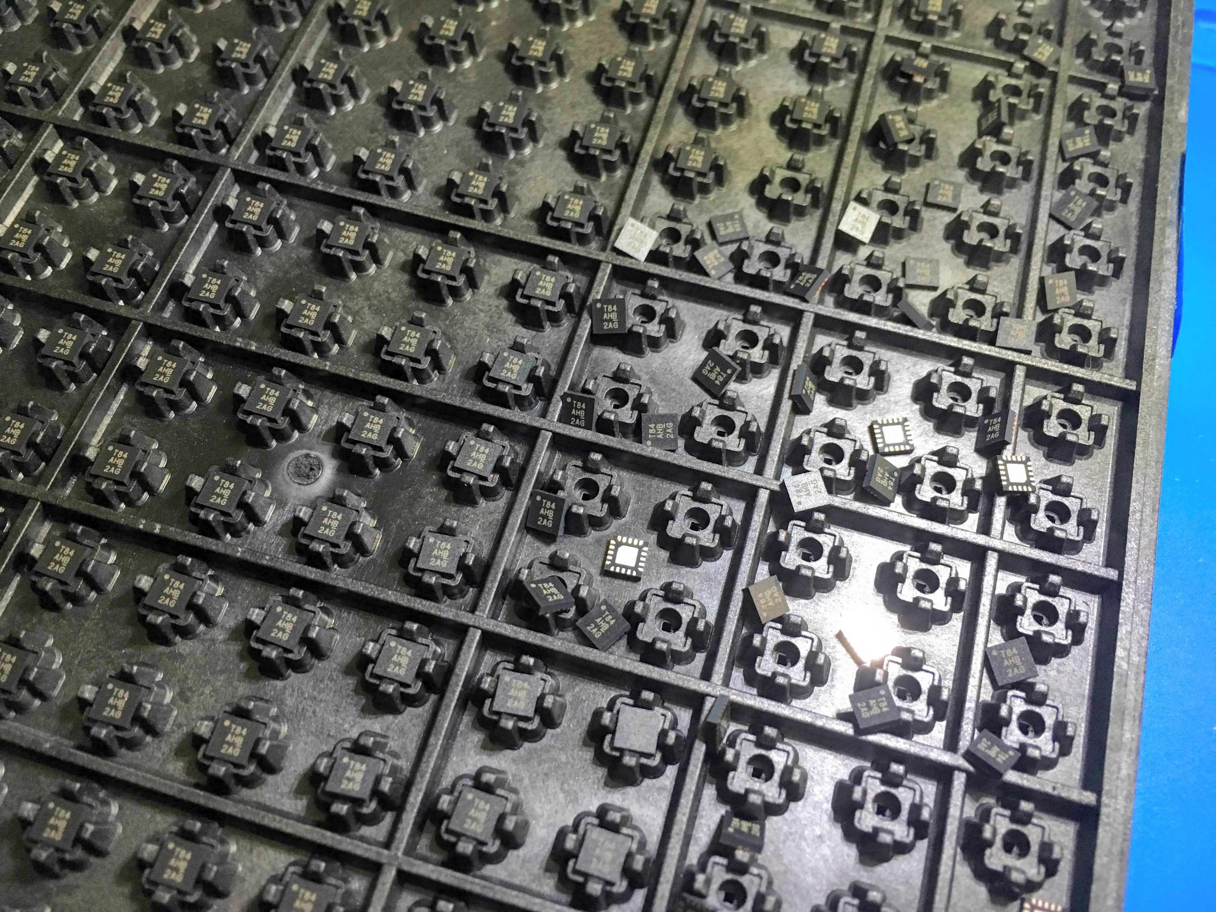
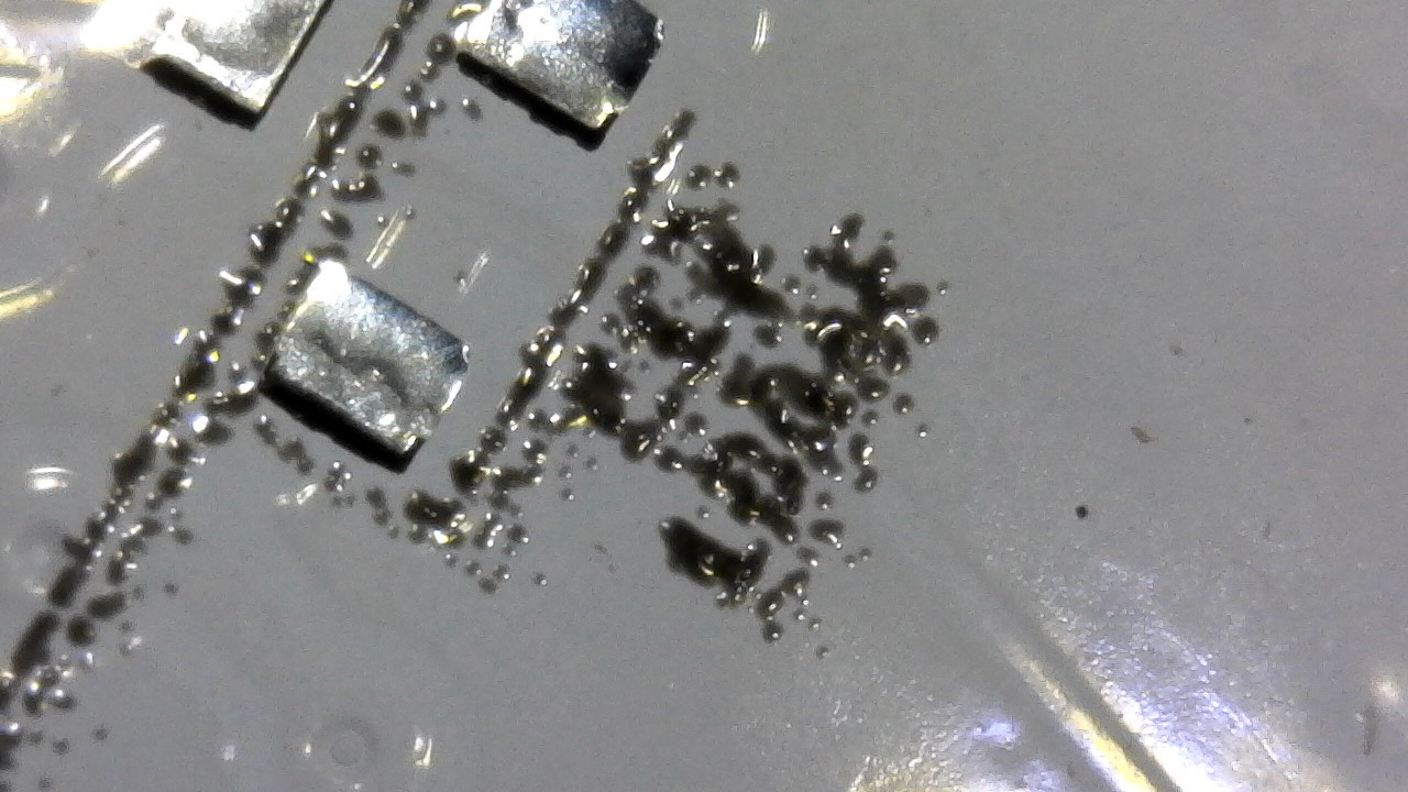
Just before I got ready to place the components I bumped into the tray of the ATtiny84a micro-chips. See here the results of bumping into the tray:
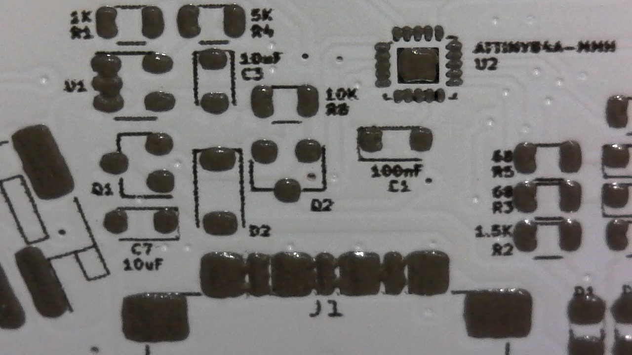
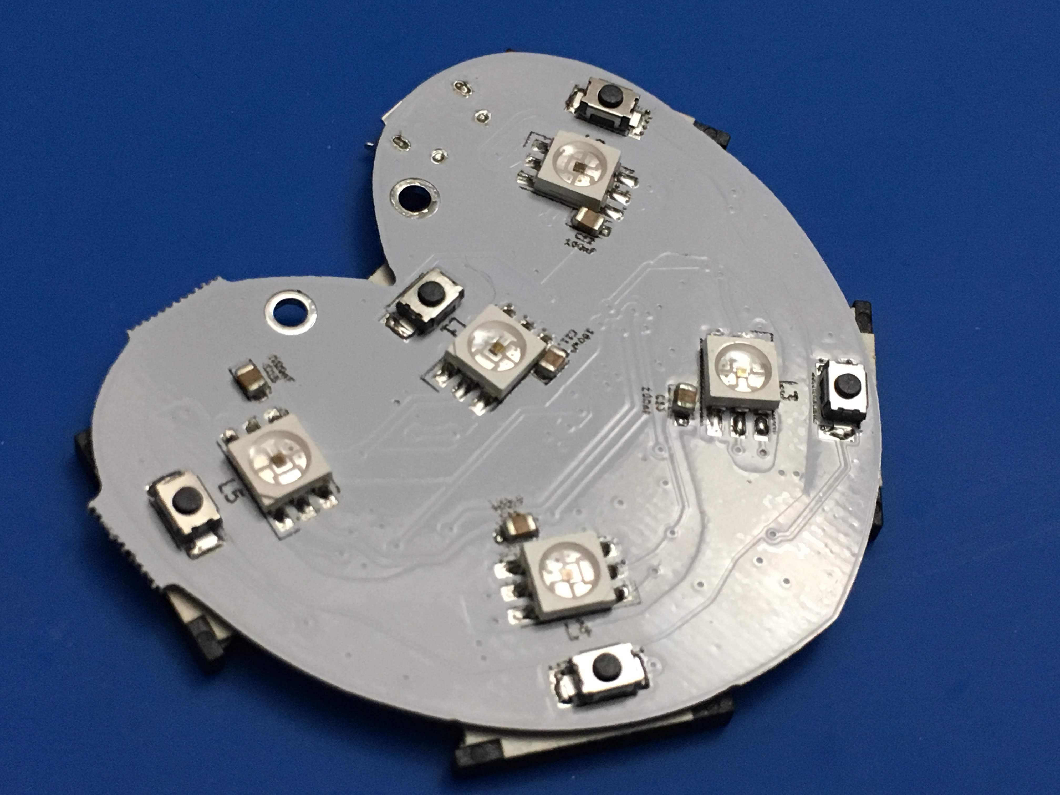
And here are some pictures of the board after placing most of the components. The battery connector and switch are still missing, but those are easy to place after they get in.
I still needs some manual touch-up since not all the LED's are connected correctly as you can see in the picture above.
Next step is uploading the firmware and check the hardware.
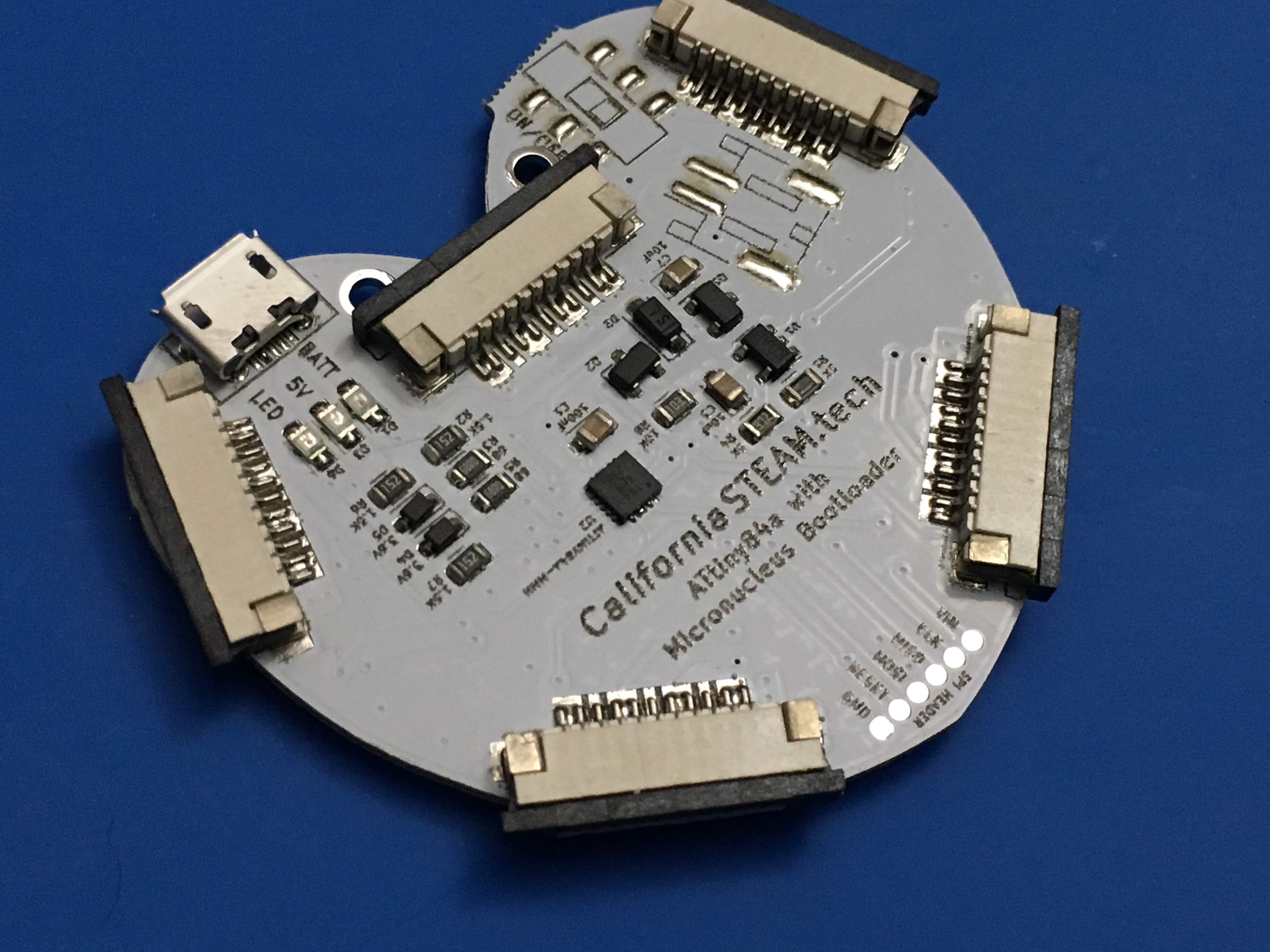
It is always exciting when the boards arrive, and you can actually hold the product. The board manufacturer contacted me a couple of days ago to let me know that the silk screen did not turn out correct, but I think it is not a big issue at this moment.
I am still waiting on some more components, and I just realized that I never ordered the on/off switch. Not a big deal, because I can use a jumper for now. All the other parts should be here before the end of the week.
For the first concept, designed with the ATSAMD21G18A, I ordered 150 boards and started putting these with a soldering iron. Soon I found out that this was going to take way too long, and so I moved to a reflow oven soon after.
Placing the components on the paste, and moving it into an oven to do the soldering did speed up the process. Unfortunately supplying the paste, even with the stencil, was messy, complicated and still took a long time.
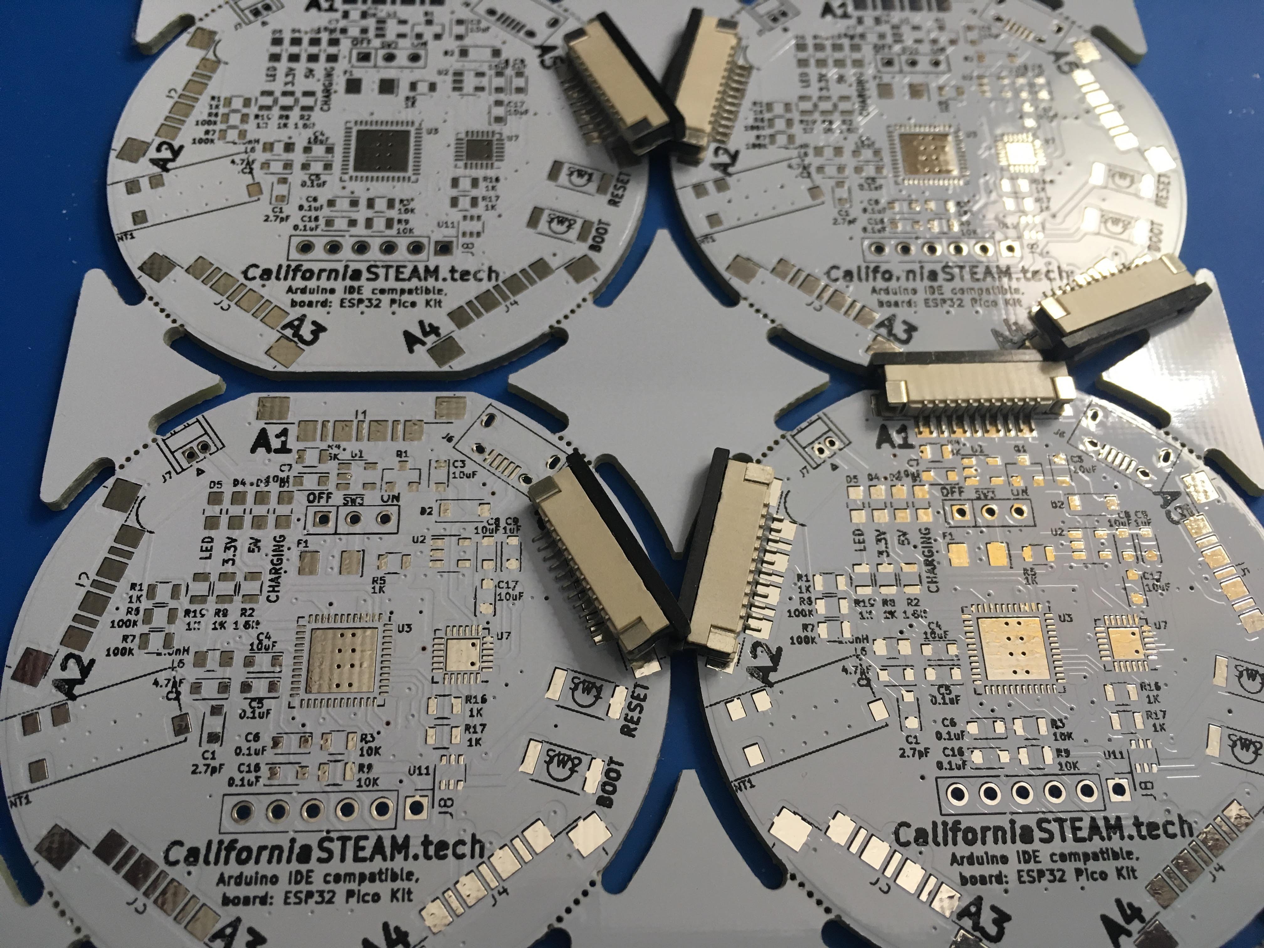
With the second concept, designed with the ESP32, I decided to order a panel instead. Since I never designed a panel before, I asked the board manufacturer to design me one. They did a great job, and it did make it so much easier to apply the paste. You actually do 4 boards at the same time, and the larger surface makes it easier to align the stencil. There was just one problem, most of the components are sticking out on this board, and these were interfering with each other.
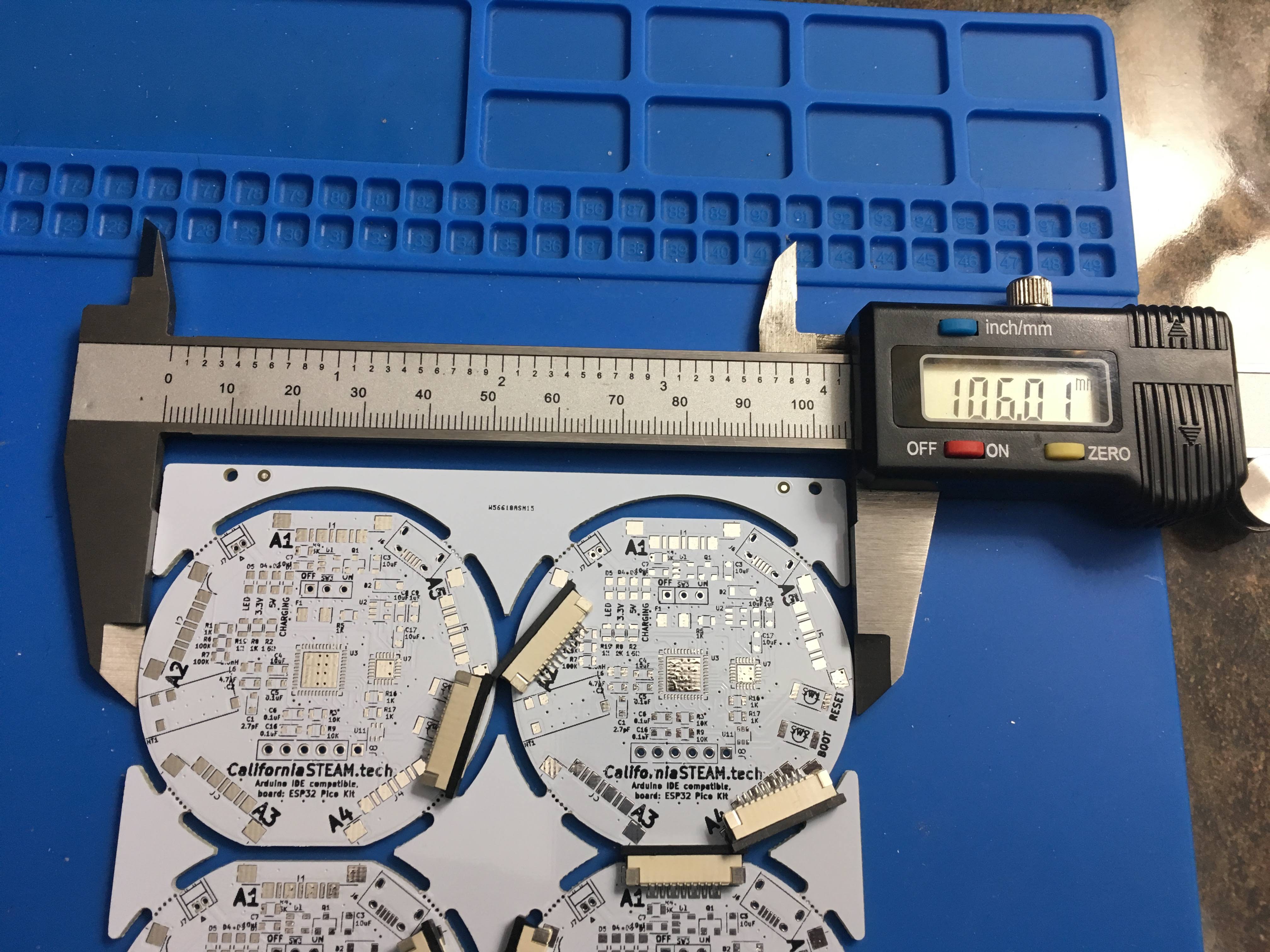
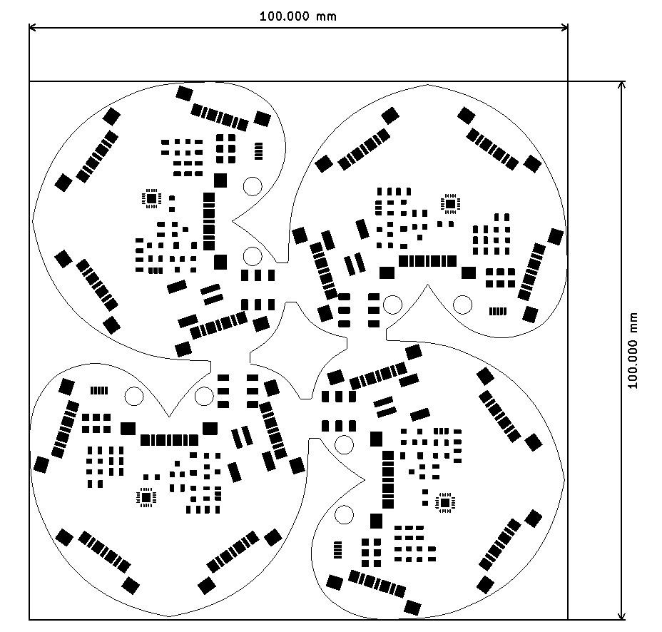
There are some very good deals for PCB manufacturing out there, as long as you stay within a 100mm square panel. The panel shown above was just a couple millimeter over, but doubled the price.
Using KiCAD to design the panel not only avoids the interference mistake shown above, it also allows you to stay within the 100mm square window, and you can even combine different designs. Depending on the manufacturer you might have to pay more for a panel, so please check carefully if a panel fee is added before placing the order.
The latest board design, with the ATtiny84a, is just a little over 50mm wide. The board cannot be redesigned for a smaller footprint since the location of the FFC connectors determine the actual size. The location of FFC is important to get about 16.7mm between the LED's (60 LED's per meter).
Fortunately the new 'hearth' design allows these boards to stack inside each other, and there was only one solution to eliminate parts from interfering with each other.
And the panel is just within the 100mm square limit:
The design is accepted by the board manufacturer, and on order. I am expecting these to finish just before the Holidays.
Initially I was planning on using the ATtiny sleep mode to turn the device off, but that will keep power on the peripherals. Apparently the APA102 chips still draw about 1 mA when not in use, and with 5 on board, this will draw the battery. A switch was added to turn off the board entirety.
On the first schematic the SPI header was missing as well which is required to upload the bootloader. I am going the use the same SPI connector I have used to program the LED earrings.
The original ATSAMD21 board used custom LED strips with integrated push buttons, one on each arm. For this concept the push buttons are located on the actual board.
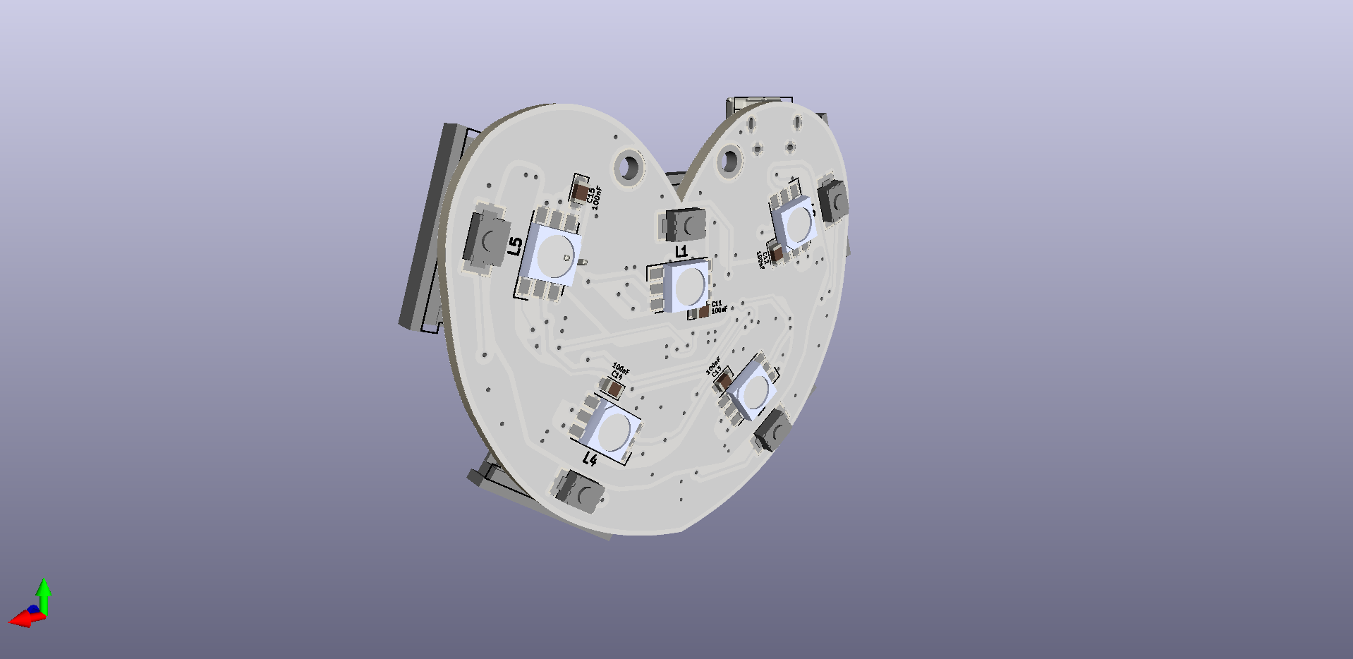
The original board was round, but now, with less and smaller parts, I am able to get to a smaller size. This allows more different shapes when used in the wearable. I was playing around with different shapes, and a heart was actually fitting all the components nicely. Instead of using traces I added some zones to get some weird shapes, giving it a different look after the soldermask is applied.
Since the board is heart shapes, some people might to wear it as is. For that reason two holes are added to the top for any type of mounting (necklace, pin etc.)
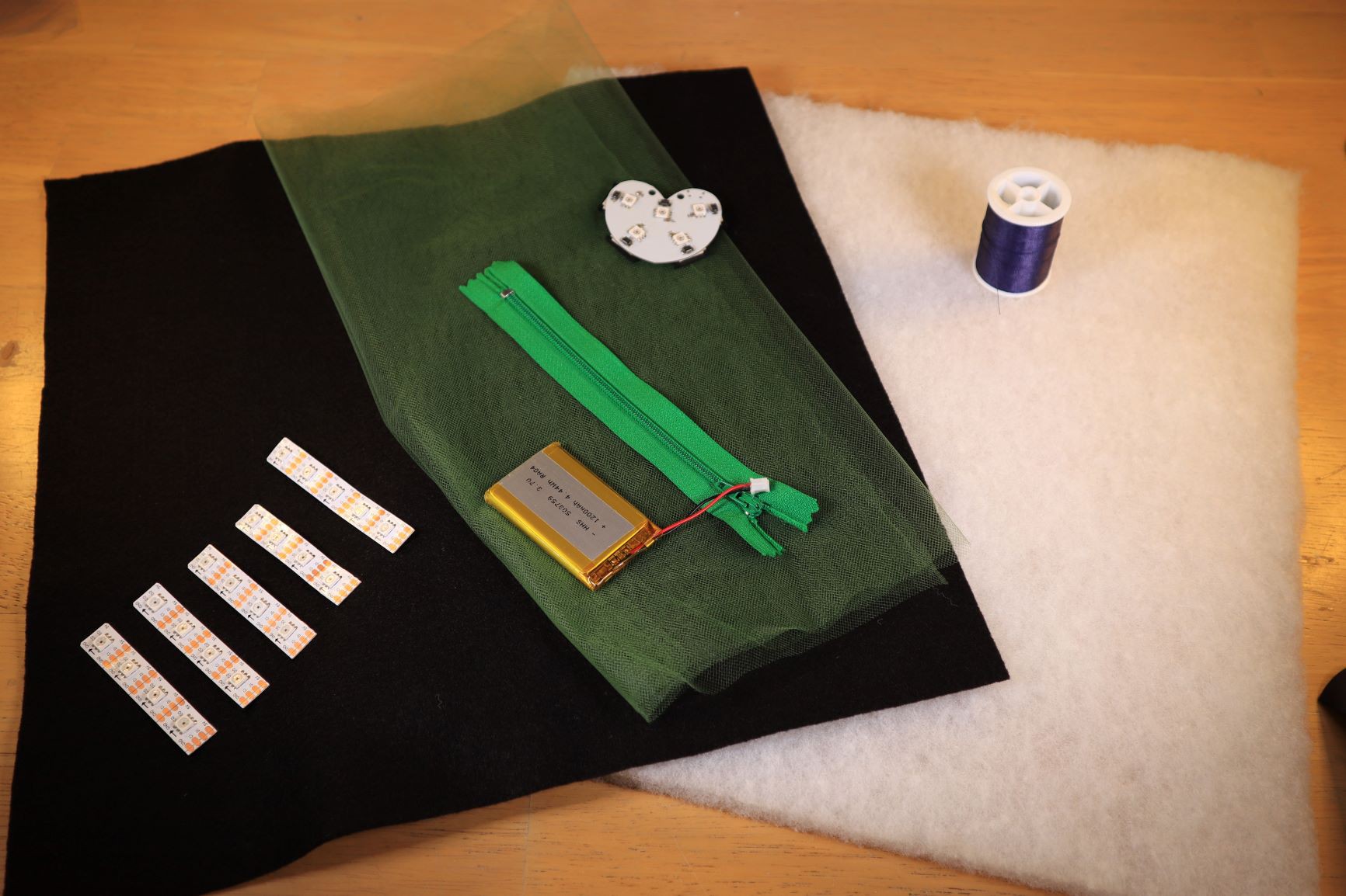
The wearables are made out of textile and use LED's, battery and control board to light it up.
Above you can find a picture of the materials used for the following instructions:
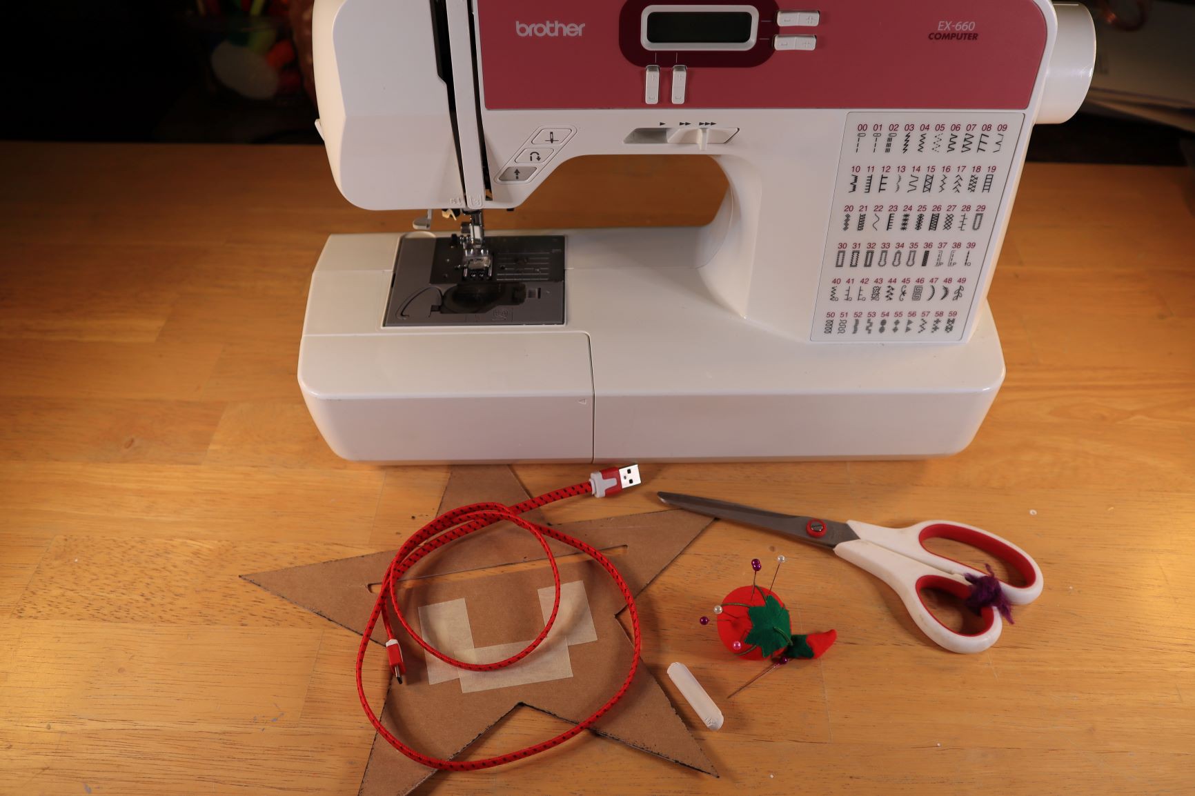
And this picture above shows the recommended tools:
You can skip this step when you use one of the existing templates.
There are tons of images online which you could use as a template or use one of the templates found above in the files. The "rainbow star" is an easy pattern to start with since it contains straight lines only. Having curves in your design makes it a lot harder.
Determine were to put the zipper or opening. For smaller wearables I usually just use an opening which I will close with a few stitches. For larger wearables I like to add a zipper to make it easier to open and close. Make the is opening big enough for the foam, board and battery which are added later. Also consider easy access to your USB charging connector.
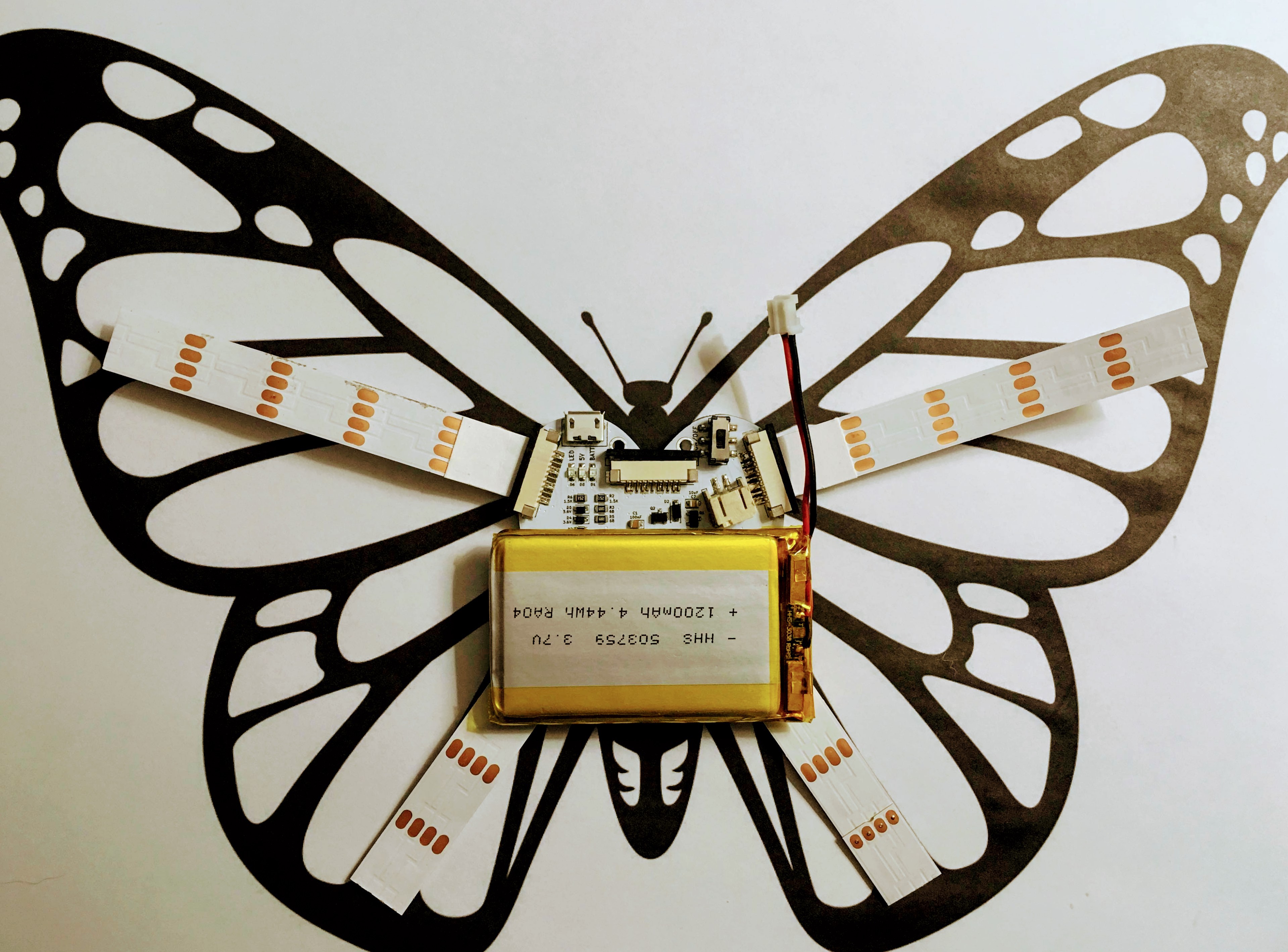
Here is an example of a butterfly I found online and I used as a sewing template:
So my zipper will be as close to the USB port and on/off switch, while a battery pocket will be as close to the bottom as possible. It will be very tight, but it will fit. This also shows how this "heart" shaped board makes it possible to make more different designs. With a regular round board, like my first designs, the board would stick out where the head of the butterfly is located.
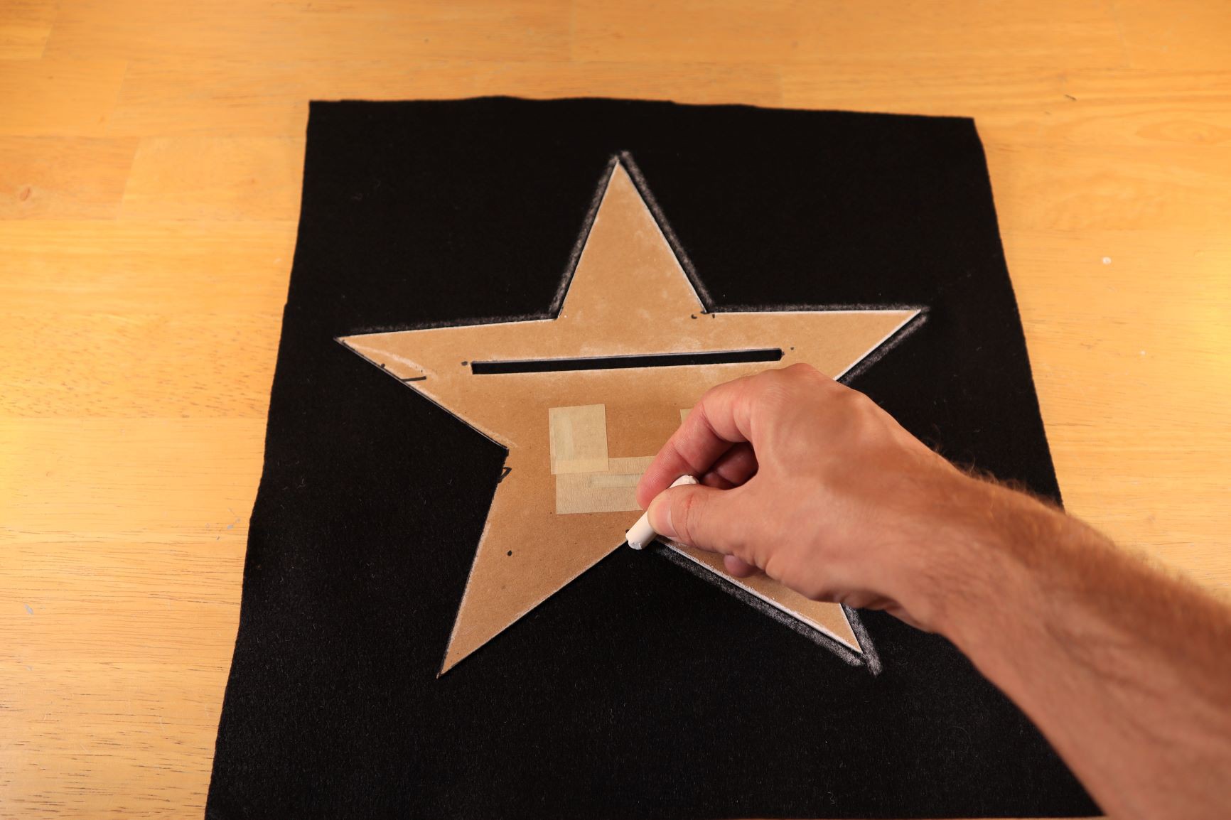
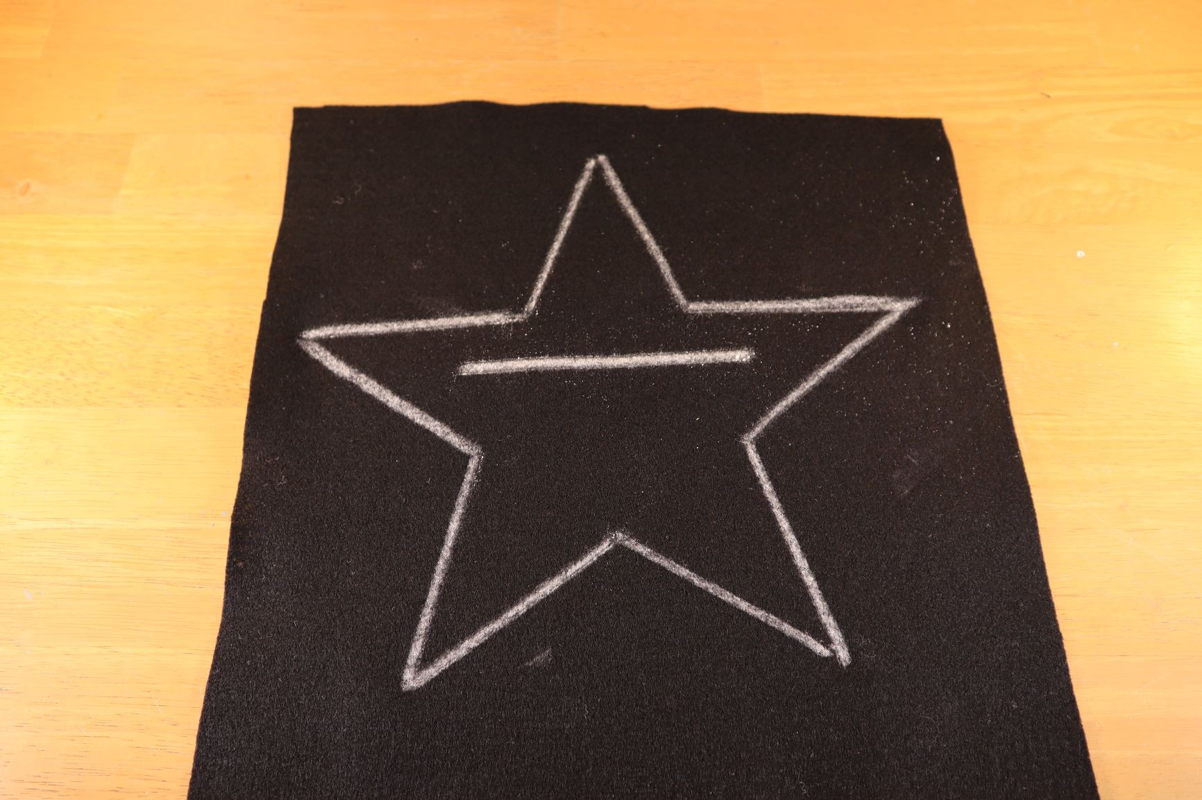
We will start with the felt which we use for the back of the wearable. Use the template (your own or the a template from the files section) to mark the outer shape and the location of the zipper.
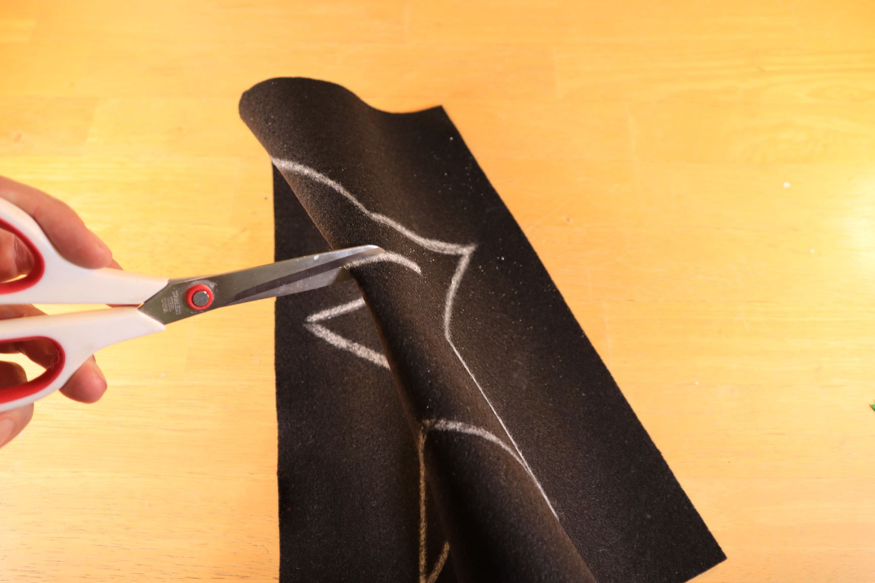
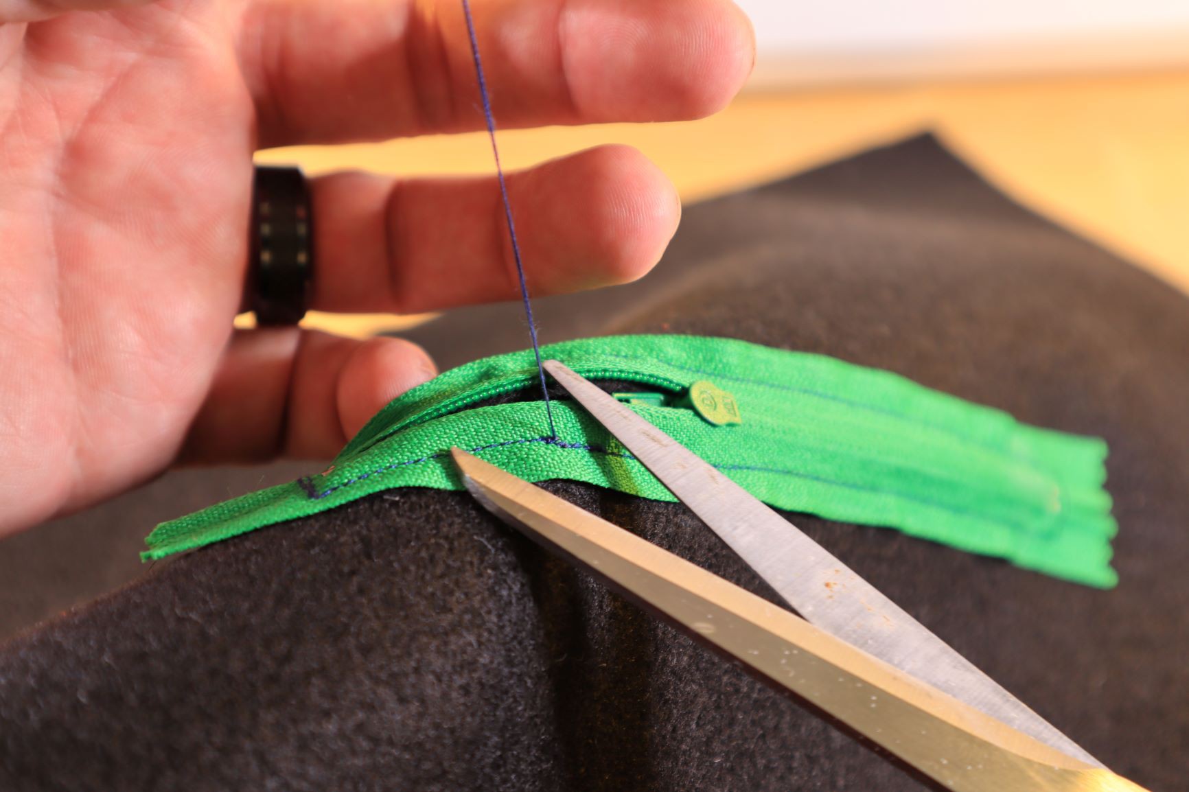
Fold the center line to make a small cut with the scissors, and make the opening wide enough to fit the zipper:
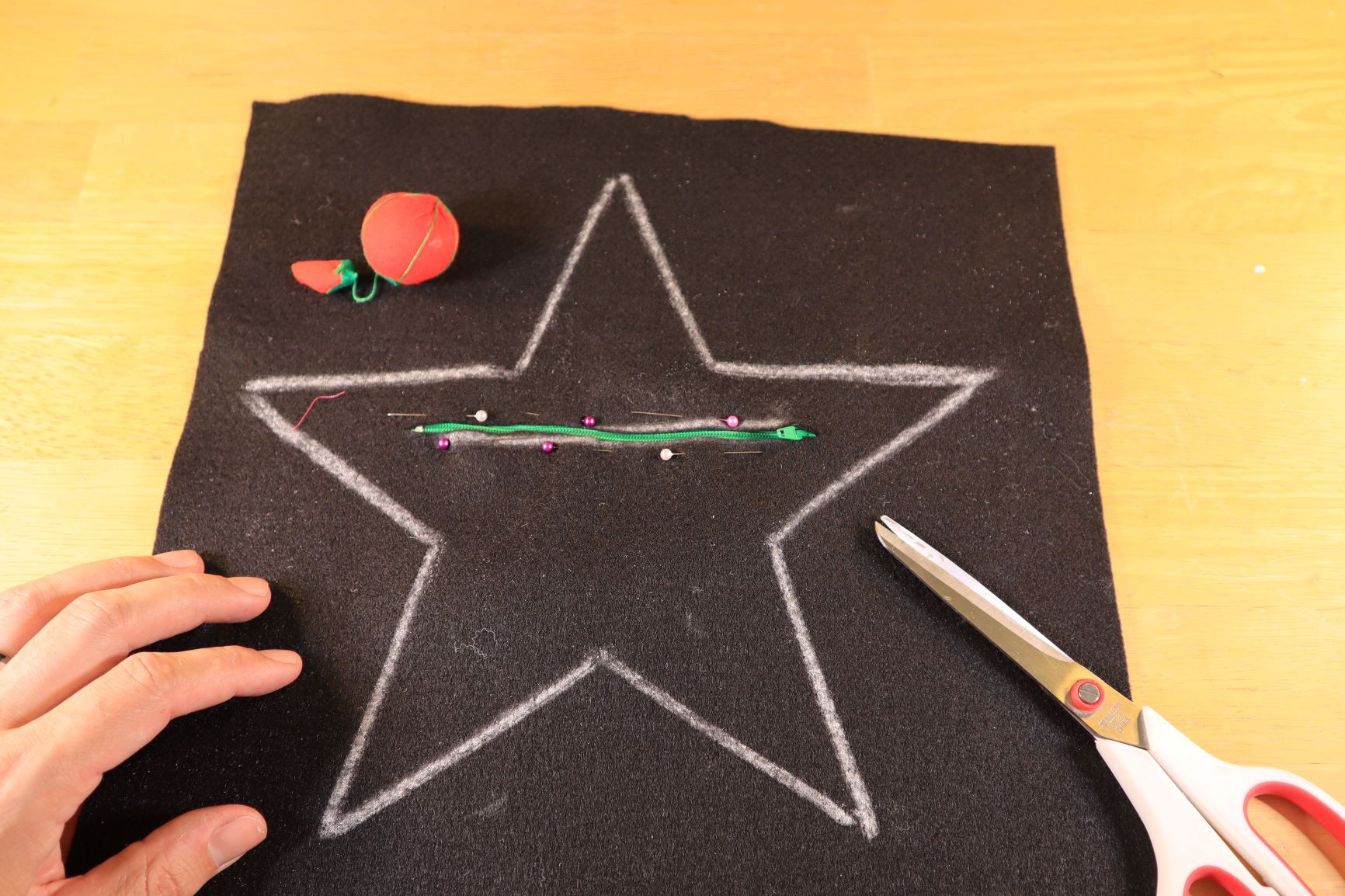
Hold the zipper in place with some pins. Note that the pins on top are inserted from the right to the left, and on the bottom from the left to the right. This makes it easier to remove the pins while we are sewing in the zipper.
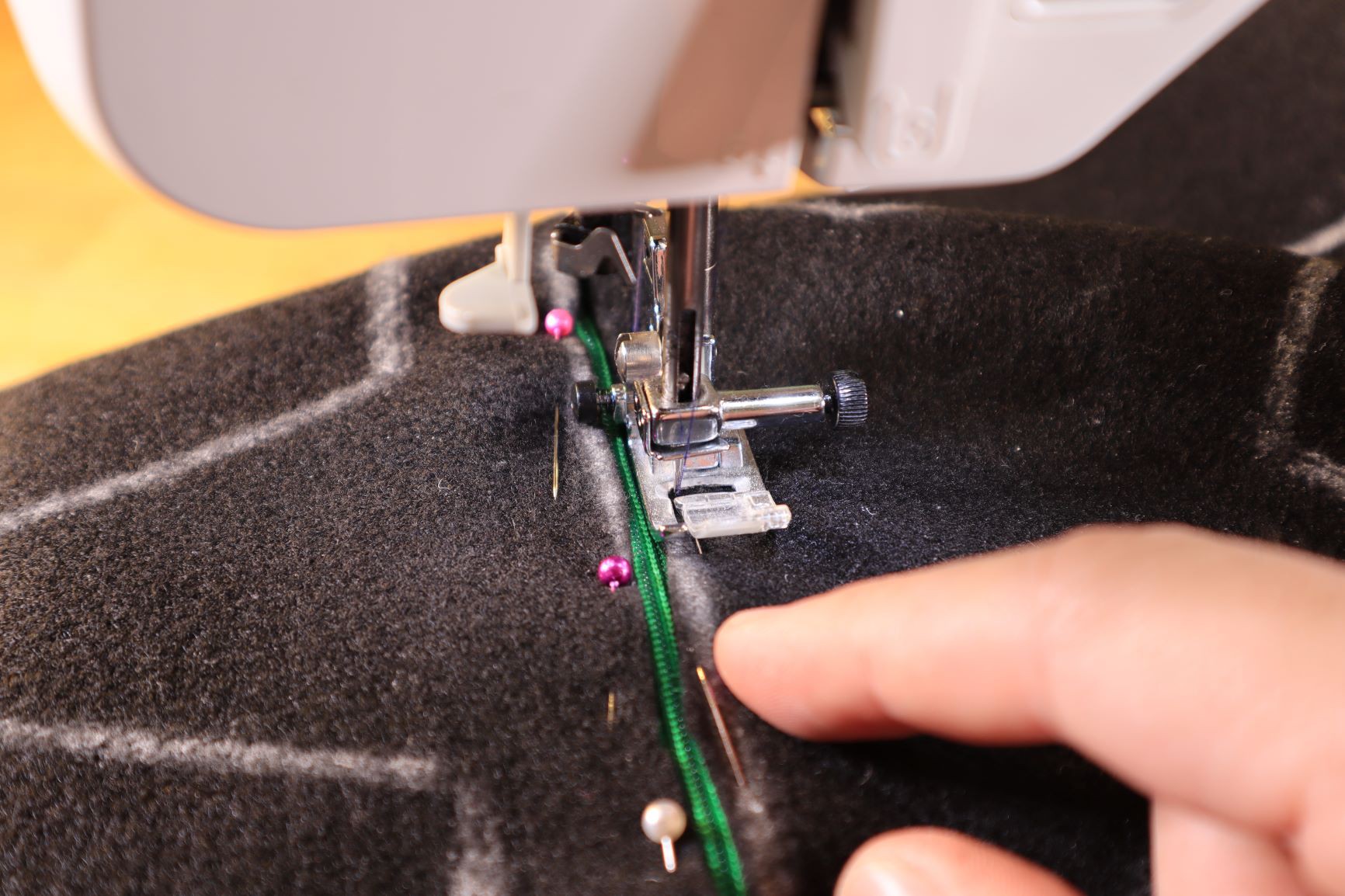
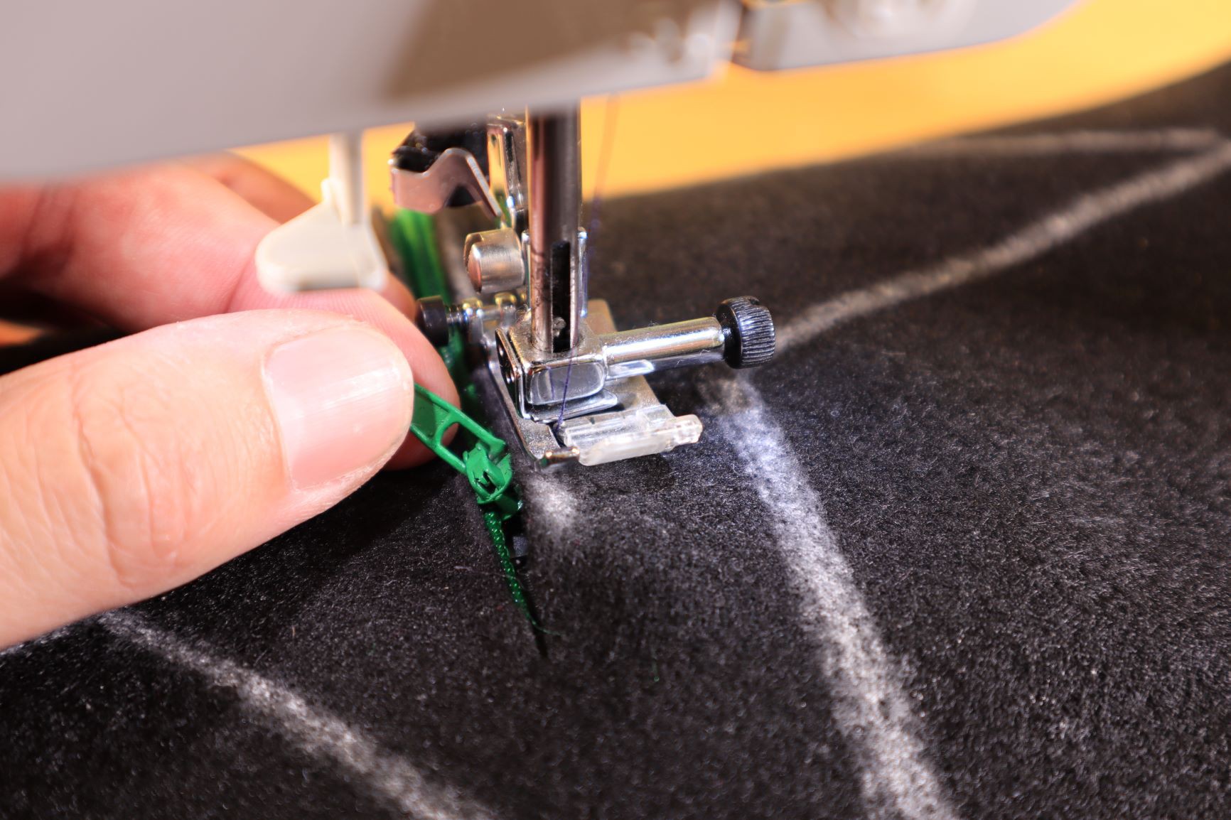
Start sewing the zipper as follows:
Just place the foot as close the zipper as possible and have the needle as far to the left as possible as well. Remove any pin that gets too close to the pressure foot. Do not sew over the pins because it might damage the needle. Sew in a straight line till you clear the end of the zipper (metal insert at the end of the zipper):
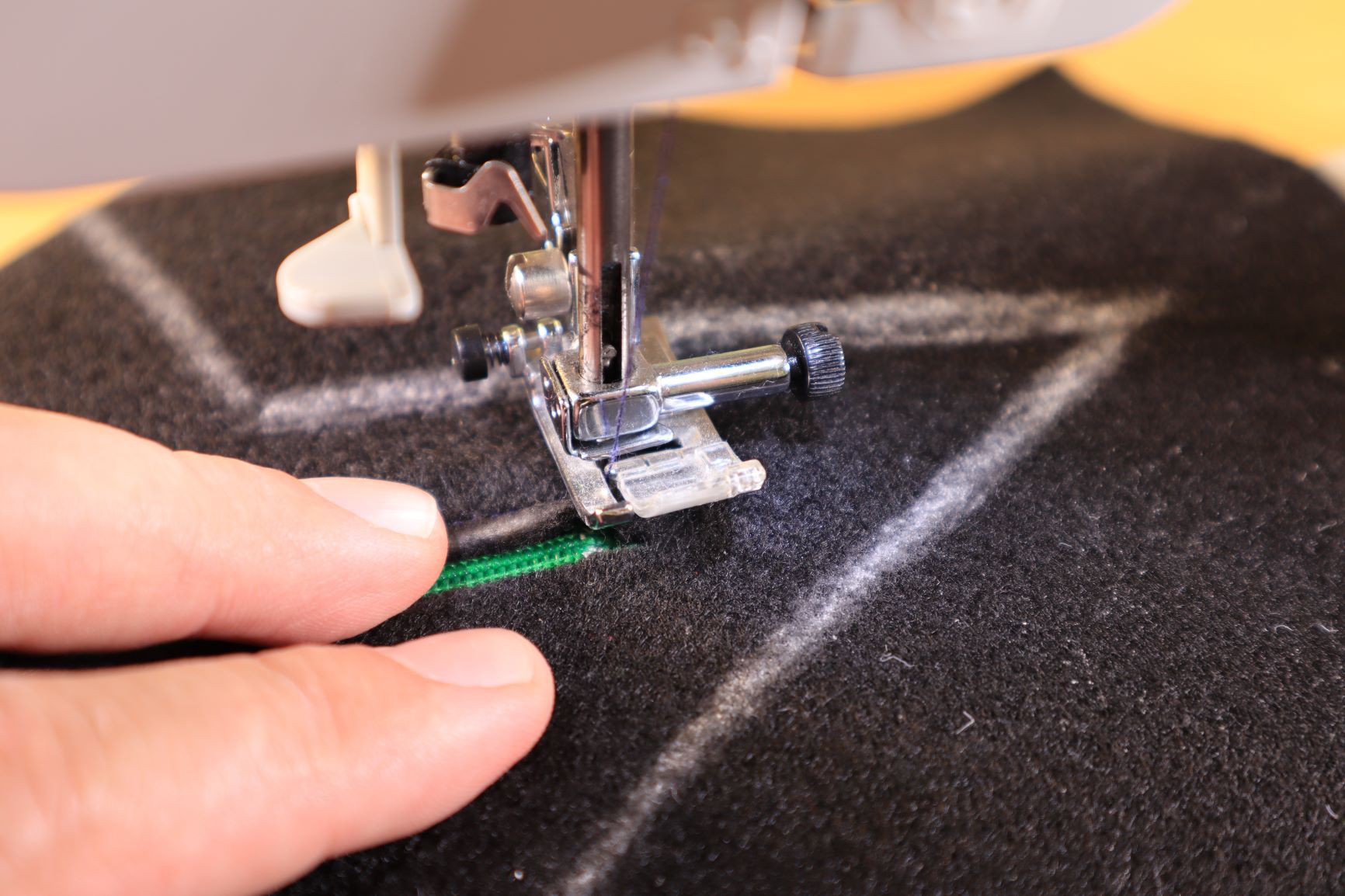
Make sure the needle is down and lift the pressure foot. Turn the fabric 90 degrees. Make sure you clear that small metal piece on the zipper, sewing over that metal piece will definitely bend or even break your needle:
Do a couple of stitches till you clear the zipper, and rotate the fabric again (with the needle in the fabric) so that you can sew the other side. Make sure that you remove the pins when you get close with the pressure foot.
When you get closer to the slider stop sewing for a second. Make sure the needle is down, bring the pressure foot up, and use the pull tab on the slider to move it down the zipper:
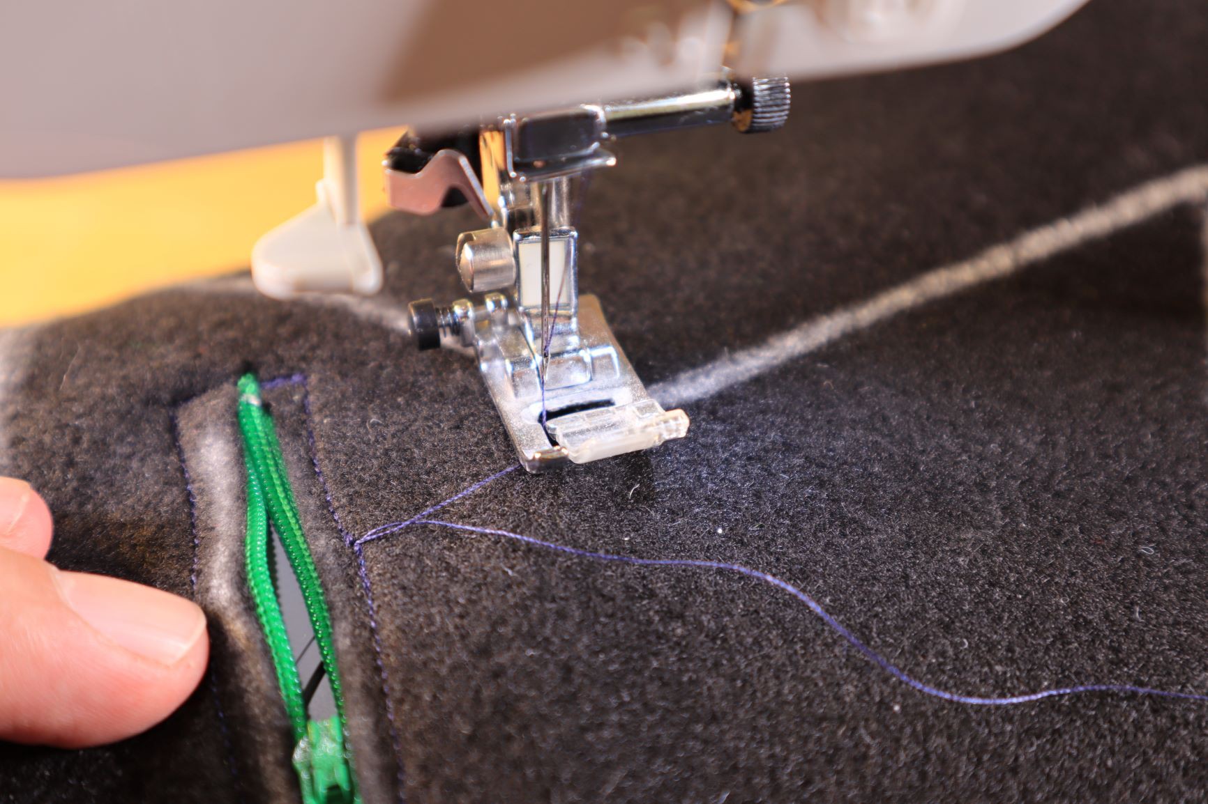
Continue sewing till the end. If you get to the end make sure your clear the end of the zipper, and turn 90 degrees again.
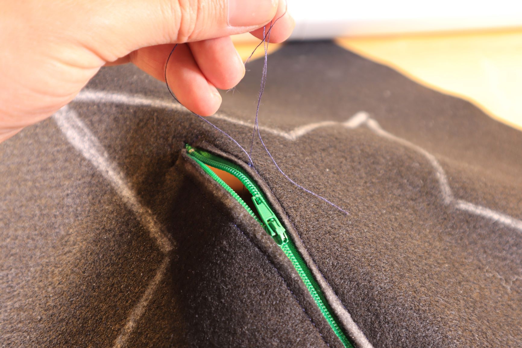
Do a couple of stitches again till it clear the zipper. Turn the fabric 90 degrees on more time and sew to the location where you started. I pull the starting thread to the side as in indicator to my starting and end point:
Knot both ends together on both sides of the fabric, and cut the ends:


I like your content admin.
https://singaporeeconomicstutor.com
Some special type of board for modular LED is available here. There are many qualities in this board. Other board and modular LED use solder but here solder is not required and people can teach their children in playground by taking help from https://www.playgroundprofessionals.com/play/parenting/5-tips-how-teach-child-make-friends-playground and get amazing hacks. This is the best quality of this board for LED.

Yeah, the Dotstars have different pinouts than some of the others... and worse, some use 12V, while others use 3.3V/5V. The documented strips are the pricey ones and you have to do your own probing on the eBay ones ;)
Adventure time :))) ps. love the butterfly - great concept and well executed!


 kiCAD panel design
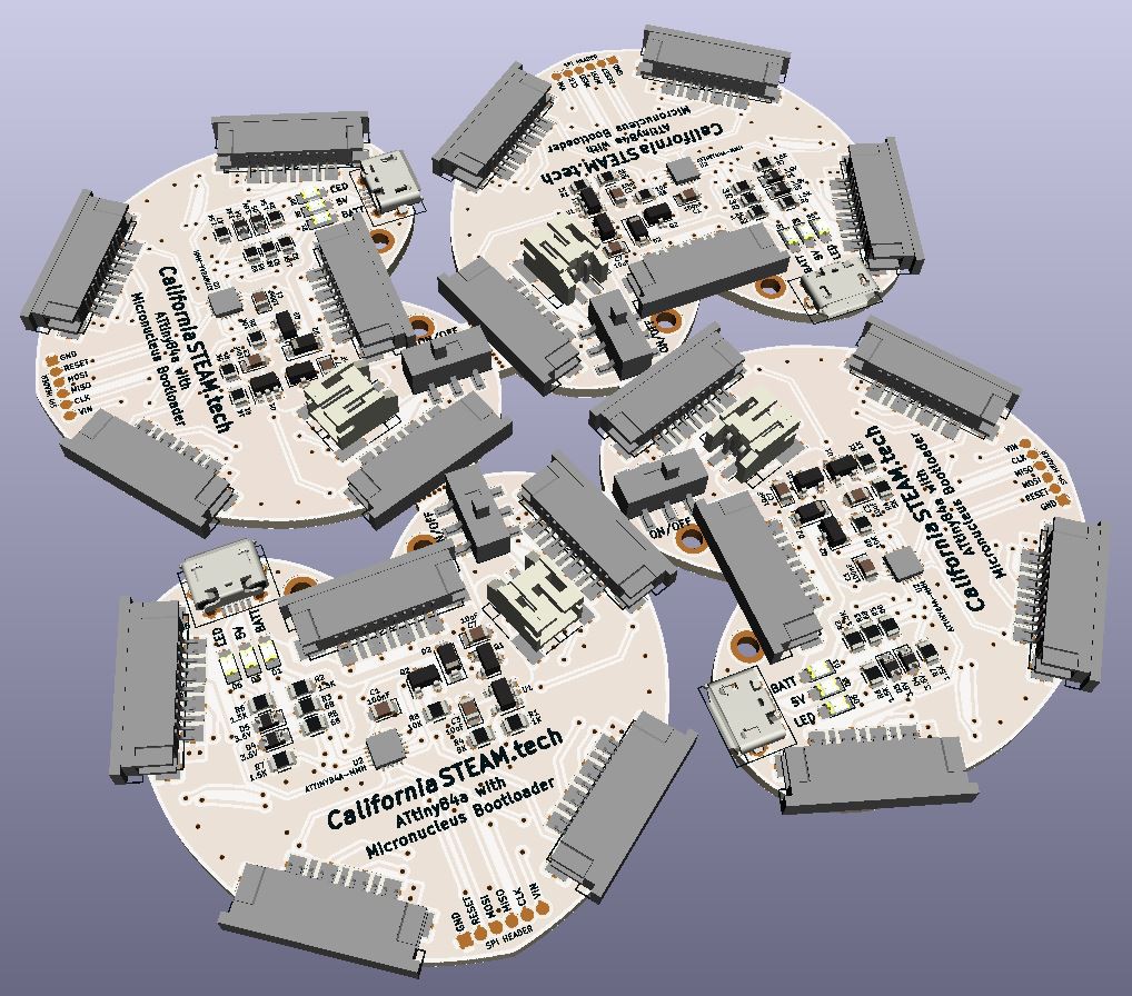


 matt thurstan
 Anool Mahidharia
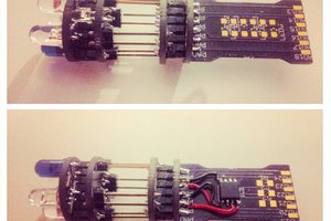
 davedarko
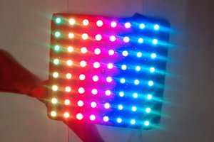
It's an awesome blog for sure.
https://jceconomicstuitionsingapore.com