 Sander van de Bor
Schematic
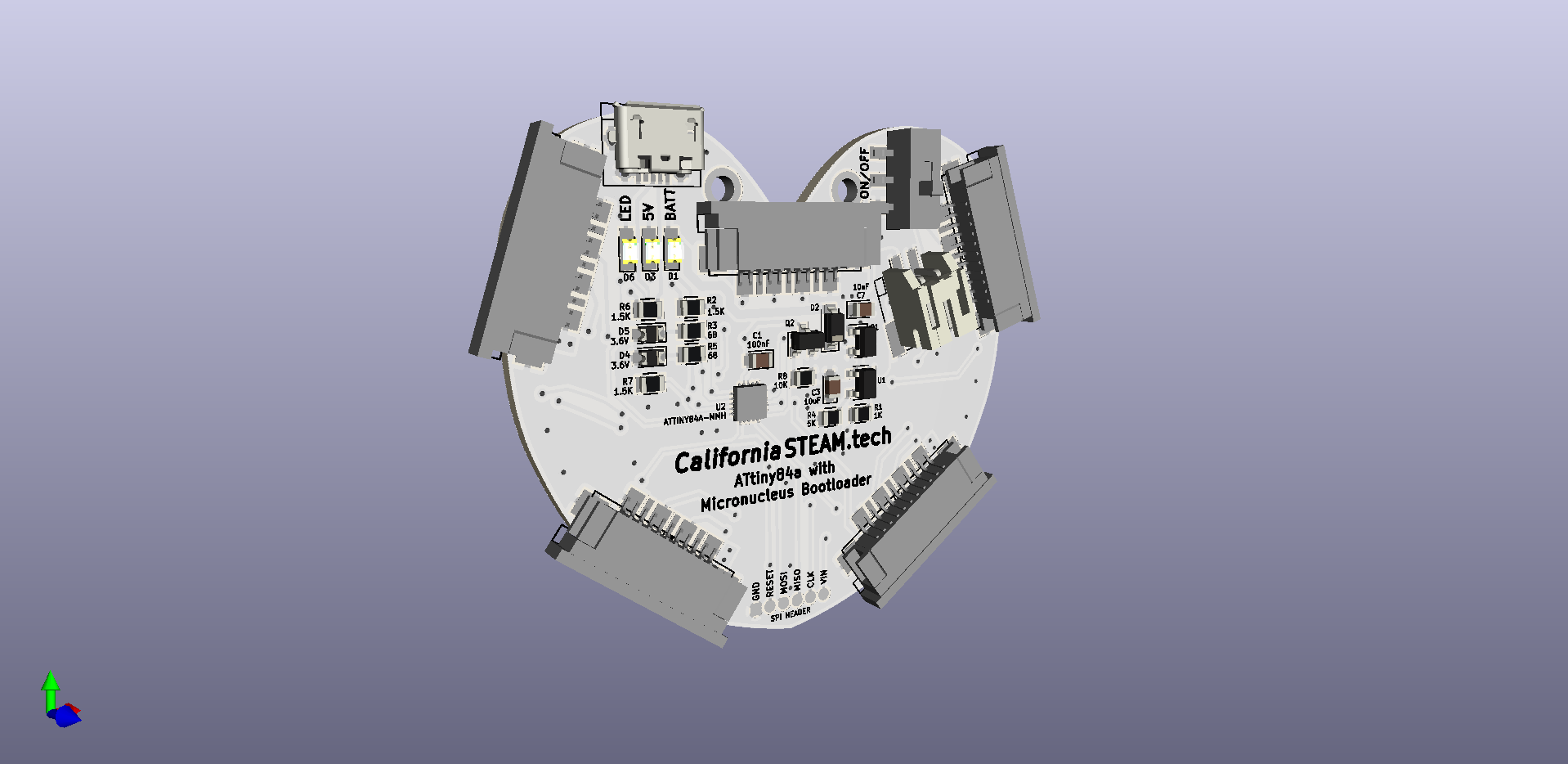
Initially I was planning on using the ATtiny sleep mode to turn the device off, but that will keep power on the peripherals. Apparently the APA102 chips still draw about 1 mA when not in use, and with 5 on board, this will draw the battery. A switch was added to turn off the board entirety.
On the first schematic the SPI header was missing as well which is required to upload the bootloader. I am going the use the same SPI connector I have used to program the LED earrings.
The original ATSAMD21 board used custom LED strips with integrated push buttons, one on each arm. For this concept the push buttons are located on the actual board.
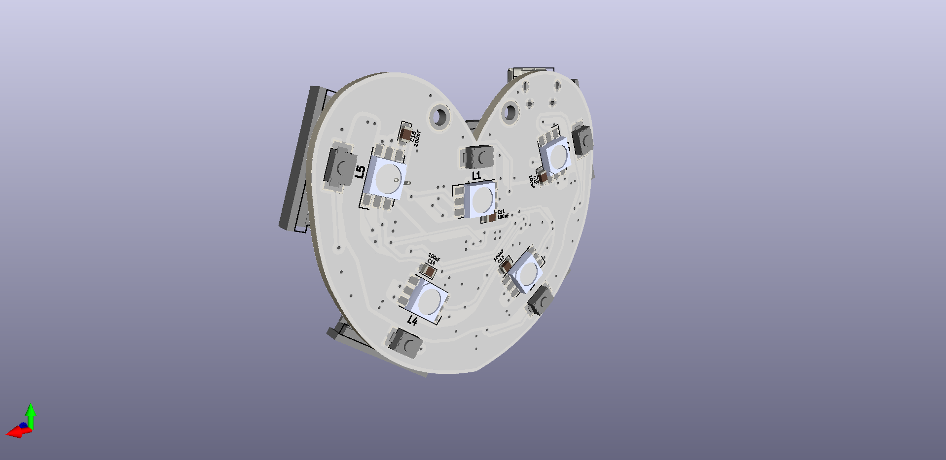
PCB
The original board was round, but now, with less and smaller parts, I am able to get to a smaller size. This allows more different shapes when used in the wearable. I was playing around with different shapes, and a heart was actually fitting all the components nicely. Instead of using traces I added some zones to get some weird shapes, giving it a different look after the soldermask is applied.
Since the board is heart shapes, some people might to wear it as is. For that reason two holes are added to the top for any type of mounting (necklace, pin etc.)
Discussions
Become a Hackaday.io Member
Create an account to leave a comment. Already have an account? Log In.