 Nikolai Ovesen
Long time no updates!
I don't even know what kinds of stuff I've gotten sidetracked on lately but for my own sanity that has been a good thing because so far there's been a lot of issues, not really unexpected when you make your first PCB and you for sure are not an electrical engineer! anyways, lets move on to the technical(ish) stuff!
PCB's without any prototyping == Failure.
It shouldn't really come as a shock but the first revision of the PCB to drive the motors in the vending machine was an absolute failure, I had managed to do a bunch of mismatches between n and p-channel mosfets, use the wrong pin order when I designed the PCB layout in kicad and I had forgotten to run the DRC before generating the gerber files and ordering it.
Epic fail!
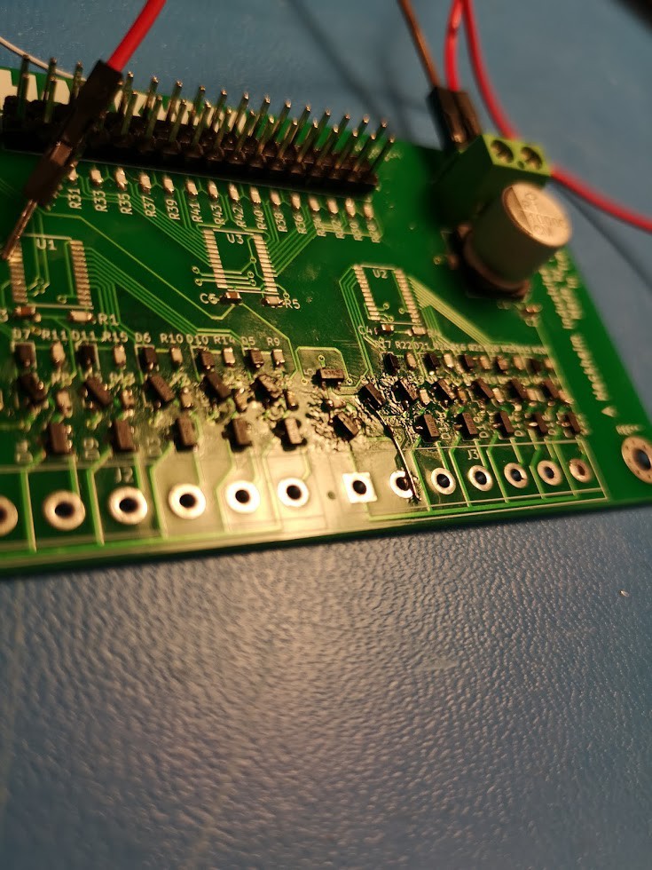
On the picture underneath here you can see the last pic I took of this PCB before I gave up on it, all the mosfets have been rotated and flipped about to make it work, still didn't work... and that is the point where I realized I had done a mixup with the N and P channel mosfets that I could not solve by flipping parts around.
A new and improved PCB design:
So, even though the first PCB was an absolute failure I learned a lot of things from it... I tried to be as efficient as possible and squeeze all the components into the smallest possible area, absolutely unnecessary when I have boatloads of free space in the machine, might as well make things eaiser to work on and JLC PCB doesn't charge more for a PCB upto 10x10cm anyways.
Apart from making the new card more spacious we've simplified the design a bit, we had a circuit to switch on/off the common positive voltage for all the engines in the machine, we removed that as it didn't really serve us any purpose.
Oh! and since last time we ordered JLC started doing matte black silkscreens and that is a HUGE plus, looks way sexier!.
So this is the new version of the PCB:
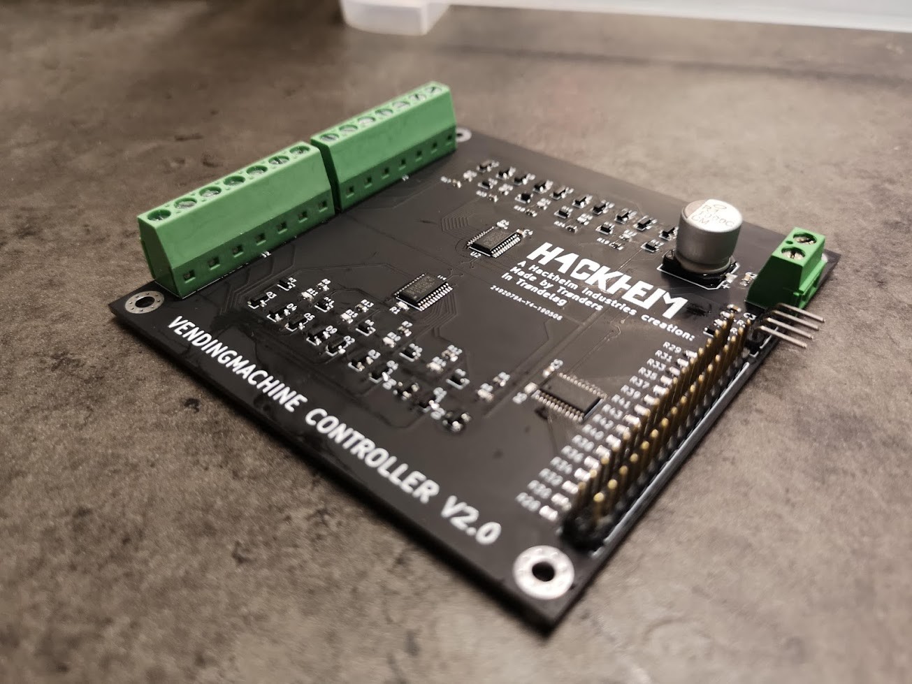
Artsy pic of it all soldered together (yeah I know its vending machine... not vendingmachine!)
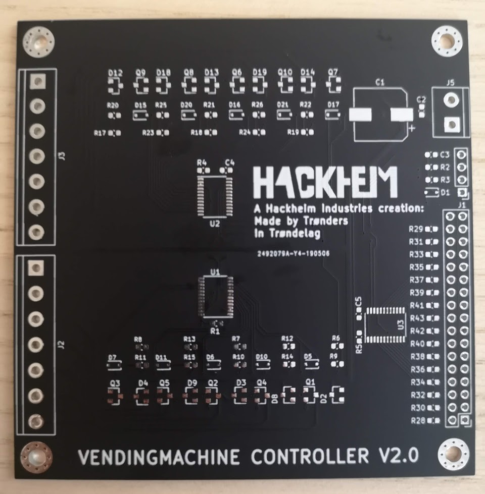
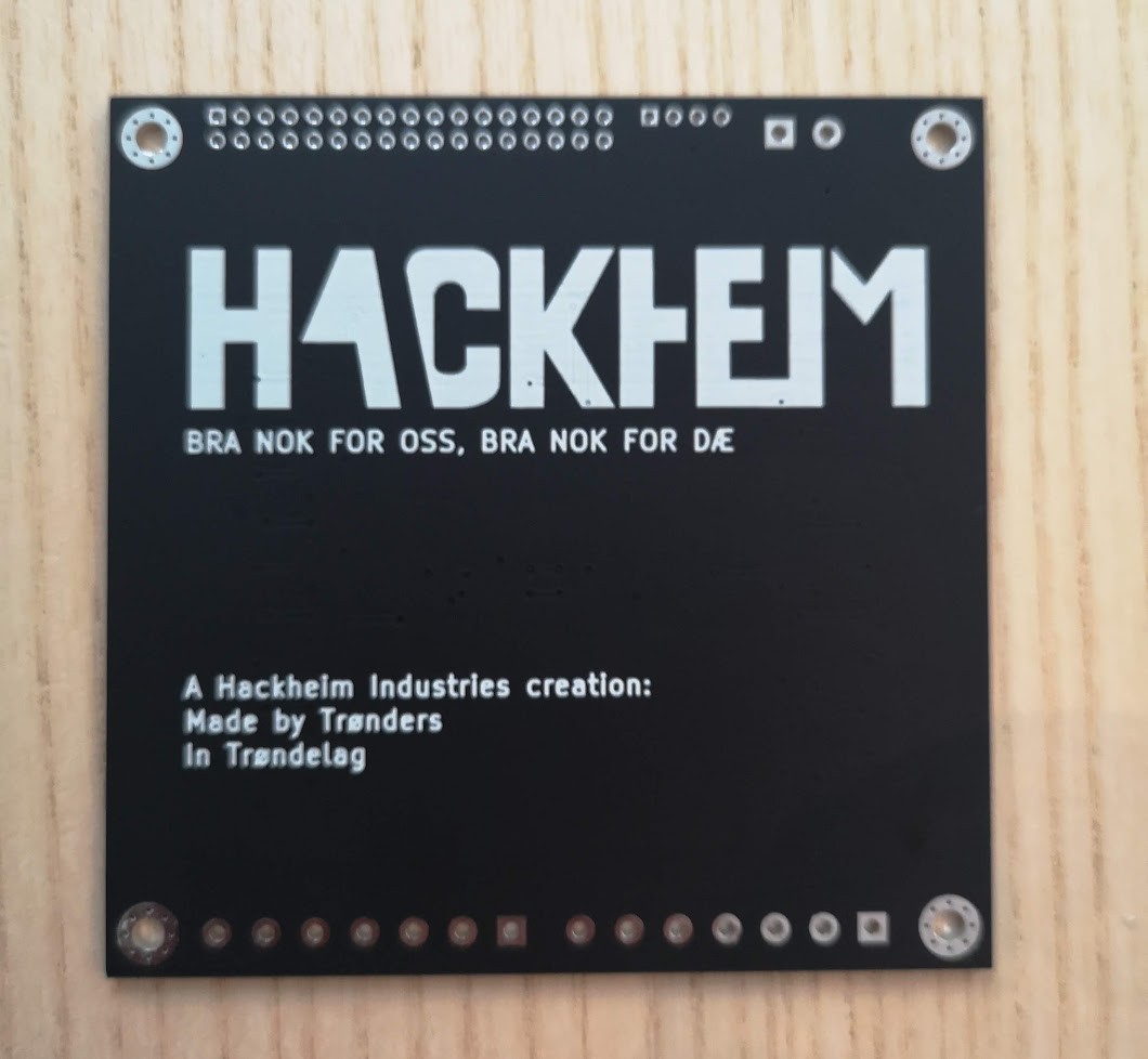
Top and bottom of the PCB's before populating it with components.
Testing/Function so far:
So so far everything seems to be working just fine;
I have soldered up one channel, got it tested and then soldered up the remaining channels and tested those and they seem to be working as intended.
I then soldered up the IO-Expanders and various other bits on the boards and after that I have only tested that I've got no short circuits and stuff going on and so far it seems to be OK.
There's only one thing we're worried about right now and that is that I forgot about having pullups on the gate of the mosfets so if the micro controller that will talk to this card uses a really long time to boot or such we might have an issue with that the pins for the motors will be floating and some degree of chaos might ensue until things are booted up.. but we'll see!
Discussions
Become a Hackaday.io Member
Create an account to leave a comment. Already have an account? Log In.