 Matthew Peverill
Ok today I'll be testing analog input. The shield has room for 20 analog inputs:
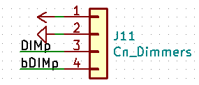
- 2 directly wired for dimmer control.
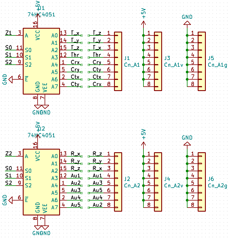
- 2 wired through 74HC4051 multiplexers.
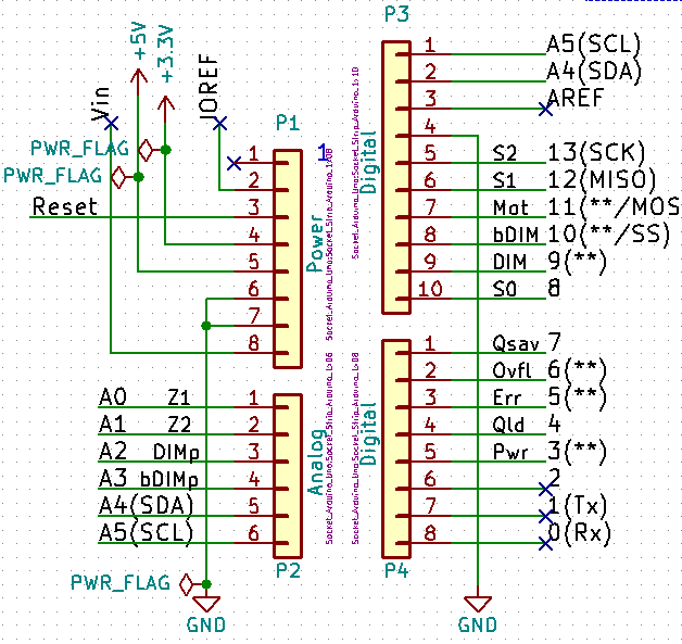
The relevant parts of the shield schematic are useful for this. Here is the pinout from the arduino:
And here are the multiplexers:
And here are the direct wires:
Test code is heavily cribbed from Sparkfun's tutorials. I've modified them to: print the additional analog inputs. Read and print both multiplexers every time pin select happens.
/******************************************************************************
Multiple Analog Mux and hardcoded input test.
Based on: "SparkFun Multiplexer Analog Input Example
Jim Lindblom @ SparkFun Electronics
August 15, 2016
https://github.com/sparkfun/74HC4051_8-Channel_Mux_Breakout"


******************************************************************************/
/////////////////////
// Pin Definitions //
/////////////////////
const int selectPins[3] = {8, 12, 13}; // S0, S1, S2
const int zInputa = A0; // Connect common (Z) to A0 (analog input)
const int zInputb = A1; // Connect common (Z) to A0 (analog input)
const int DIMp = A2;
const int bDIMp = A3;
void setup()
{
  Serial.begin(9600); // Initialize the serial port
  // Set up the select pins as outputs:
  for (int i=0; i<3; i++)
  {
    pinMode(selectPins[i], OUTPUT);
    digitalWrite(selectPins[i], HIGH);
  }
  pinMode(zInputa, INPUT); // Set up Z as an input
  pinMode(zInputb, INPUT);
  pinMode(DIMp, INPUT);
  pinMode(bDIMp, INPUT);

  // Print the header:
//  Serial.println("Y0\tY1\tY2\tY3\tY4\tY5\tY6\tY7");
//  Serial.println("---\t---\t---\t---\t---\t---\t---\t---");
}

// The selectMuxPin function sets the S0, S1, and S2 pins
// accordingly, given a pin from 0-7.
void selectAMuxPin(byte pin)
{
  for (int i=0; i<3; i++)
  {
    if (pin & (1<<i))
      digitalWrite(selectPins[i], HIGH);
    else
      digitalWrite(selectPins[i], LOW);
  }
}

void loop()
{
  // Loop through the hard wired dimmers
  Serial.print(String(analogRead(DIMp))+" ");
  Serial.print(String(analogRead(bDIMp))+" ");
  // Loop through all eight pins.
  for (byte pin=0; pin<=8; pin++)
  {
    selectAMuxPin(pin); // Select one at a time
    int inputValuea = analogRead(zInputa); // and read Z1
    int inputValueb = analogRead(zInputb); // and read Z2
    Serial.print(String(inputValuea) + " " + String(inputValueb) + " ");
  }
  Serial.println();
}
Unfortunately, when I first turned on the Arduino's serial plotter, this is what I get when I turn one of my throttle potentiometers (nothing else does anything):
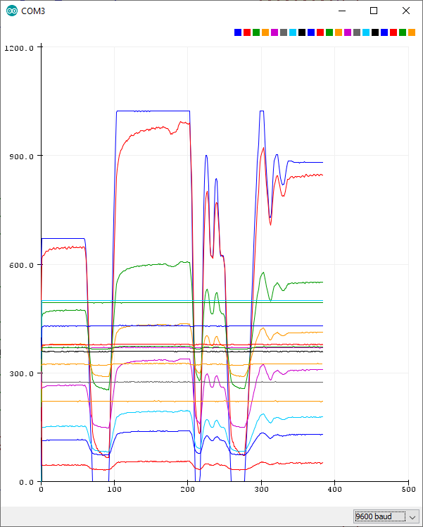
Ok first let's cut out everything but the dimmer pots (A2-A3):
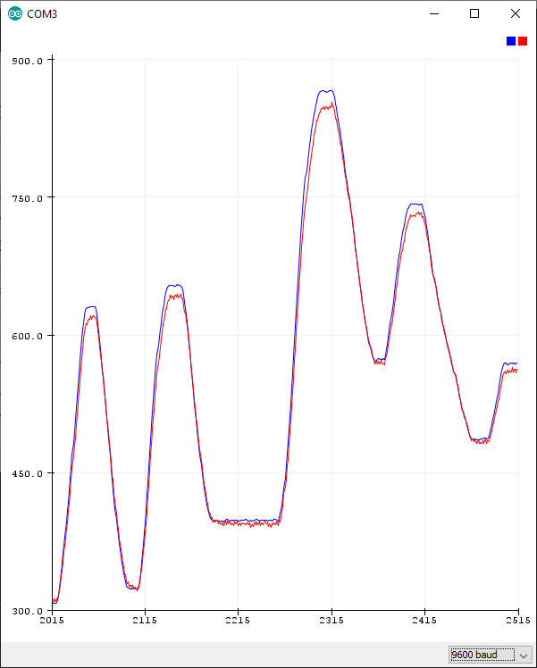
These should not be in sync! Ok so now we need to know if there is an issue with the shield or with the jury-rigged protoboard I have the pots hooked up to. I plugged said board in to the other arduino and got exactly the same result. So probably something dodgy with the protoboard, which is not surprising because it's a mess.
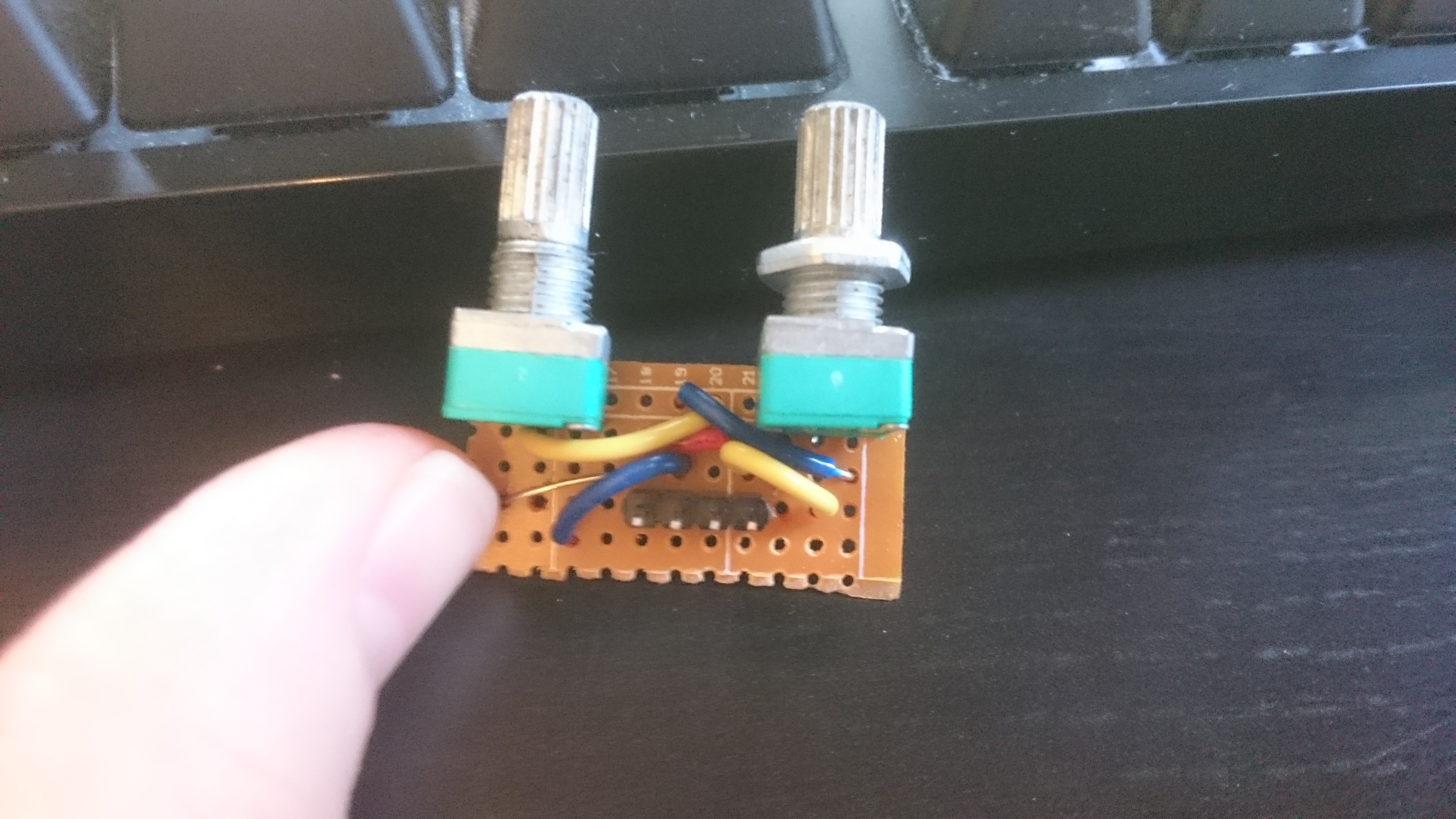
OK, but what about the multiplexers? Even without the dimmer pots plugged in, we get a horrible mess:
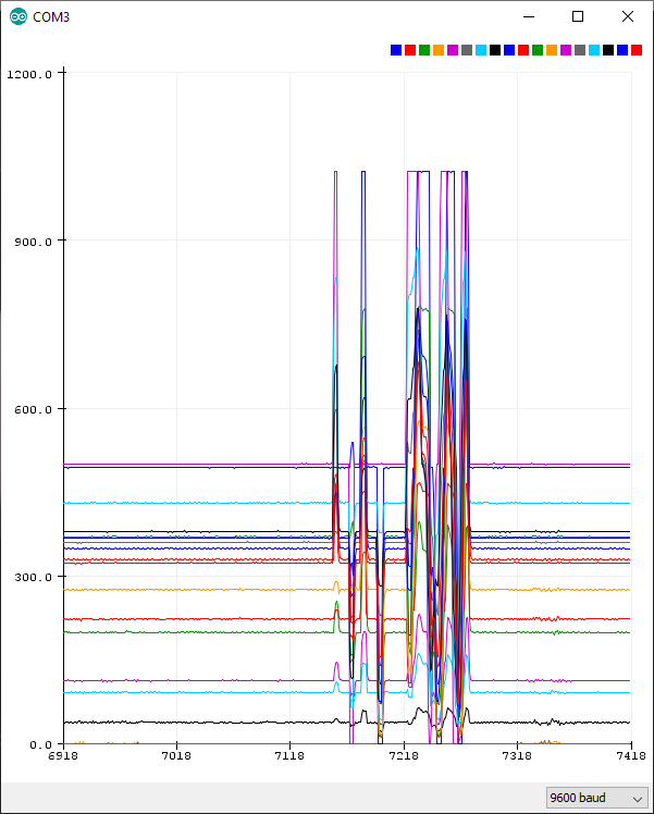
Only one joystick seems to do anything, and what it does is move all the analog pins at once. What's happening here is that the other analog pins are just open (because I only plugged in the 2 pins from the joystick). If you ground them, then suddenly the output looks much more sensible:
Good news! The circuit on the shield seems to work just fine.
Discussions
Become a Hackaday.io Member
Create an account to leave a comment. Already have an account? Log In.
May I ask why you went for Analog Multiplexers?
They can be useful in certain situations, but for this scenario I would have probably used one or two 16 channel I2C ADCs
They would fulfill a similar function, would hopefully be fast enough, and would remove any possible crosstalk or analog problems by going to digital signals ASAP.
The weird readings from the open analog pins with no connection is perfectly normal behavior, by the way. That's mainly because the analog "Sample and Hold" circuit retains a bit of charge from the last reading, if the input impedance of the analog pin is very high.
Let's hope you can find the problems - this IS pretty cool stuff, after all!
Are you sure? yes | no
TBH, I didn't know you could get those. I'm guessing you mean something like this one: https://www.mouser.com/ProductDetail/Analog-Devices/LTC2497CUHFPBF?qs=sGAEpiMZZMtgJDuTUz7Xu%252B83NC4B1t7jPYXDEXvhAAC3ftEcg32X3g%3D%3D
That would be more consistent with the rest of the architecture (everything else is i2c) and would save more room on the board. It does look like they are a bit more expensive than this option.
Are you sure? yes | no