 Matthew Peverill
PCB development is ongoing! After talking to the amazing Kicad forum people about how to design an amateur-friendly PCB without soldermask, I was convinced that I should just send a design to a board house. This means I want to be extra sure my circuits work, which means prototyping things on breadboard.
Parts of the circuit I'm quite comfortable with (I2C I/O expanders, switches with pull-up/pull-down resistors). BUT there are two parts that are a little less comfortable. One is the vibration motor, which I'll address next time. The other is LED control.
My design calls for some LEDs to be driven off the arduino directly for maximum fail-safe capability in the event of a hardware problem (power, error, overflow). Other LEDs are to be driven by ULN2803A darlington pair arrays. The basic premise of these latter is to allow the microcontroller to control logic while providing steady current (and avoid drawing too much current through the controller chips and burning them out.
Now, the complications are that we also want:
- A PWM dimmer control wire that is common to all LEDs on the board.
- A 'lamp test' circuit that turns on all LEDs through a hardware switch when pressed.
The latter is easier. We just use diodes to provide alternate current to the anode when a button is pressed, which effectively over-rides the arduino pin. You need another set of diodes connecting the arduino to the anodes, so that you don't short out the arduino pins (fun fact - my arduino didn't burn out when I did this the first time, but it did cause flickering when the lamp test was on). In the case of the ULN, you can hook up the common emitter pin to ground the switch. When the switch hooks to ground, the common emitter is grounded and all the LEDs light.
The PWM is more tricky. For the board controlled lights, you can just map an analog in to the PWM pins and, presto, you're good to go. BUT I don't have enough PWM pins to drive every LED. Instead we use some transistor trickery to turn off the ground pin on the ULN using a common PWM pin. Full disclosure: I don't fully understand how this works and, like a lot of my project, it's cribbed from Petewasere's github page.
OK so I bought an adafruit metro mini so I don't have to unplug my arduino from the panel (almost got the M4 version, but I wanted an equivalent). I soldered on the pins and plugged it in my breadboard. My soldering is decidedly just ok:
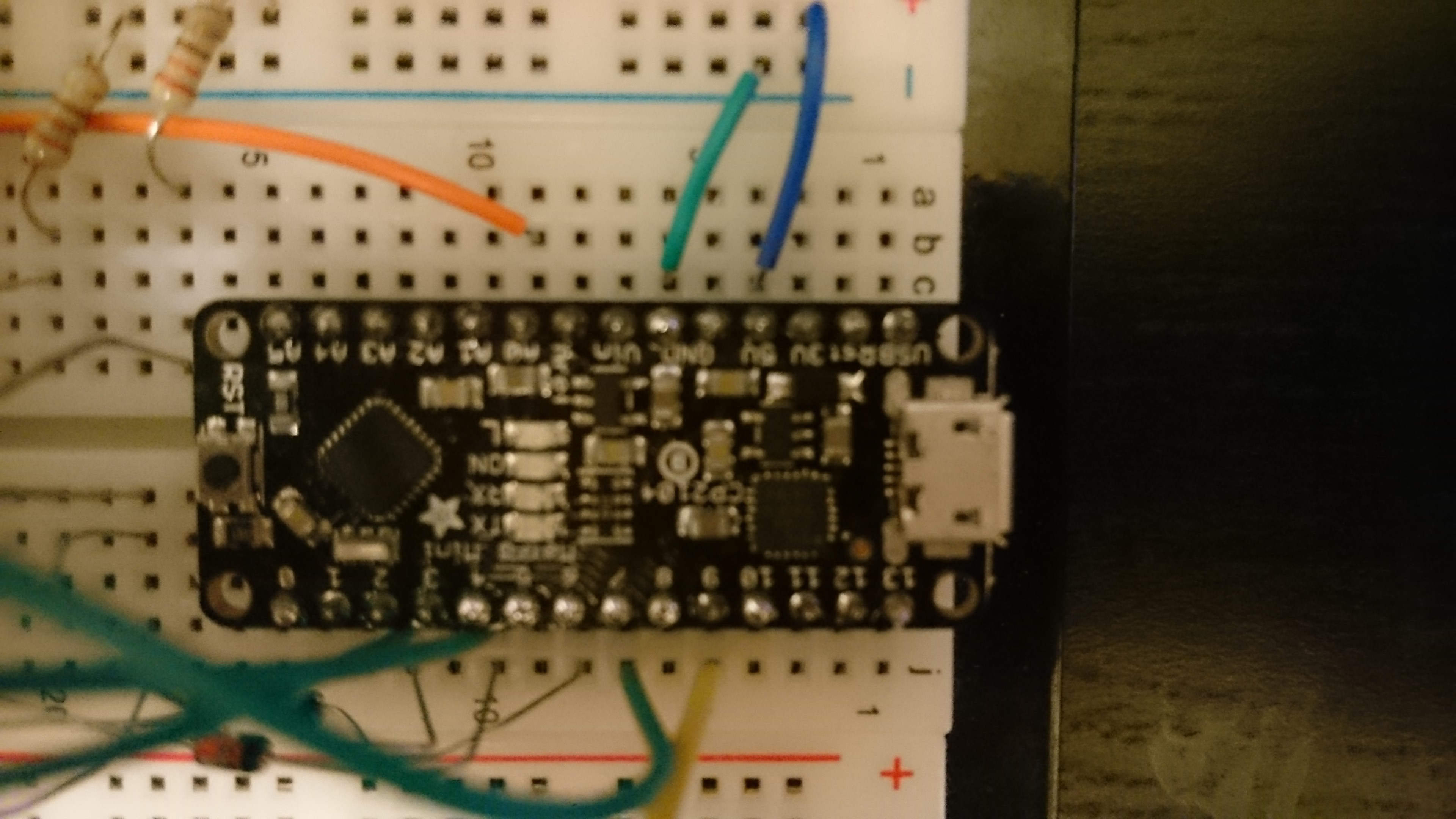
Look at those blobs! Seriously those this thing is great for breadboarding.
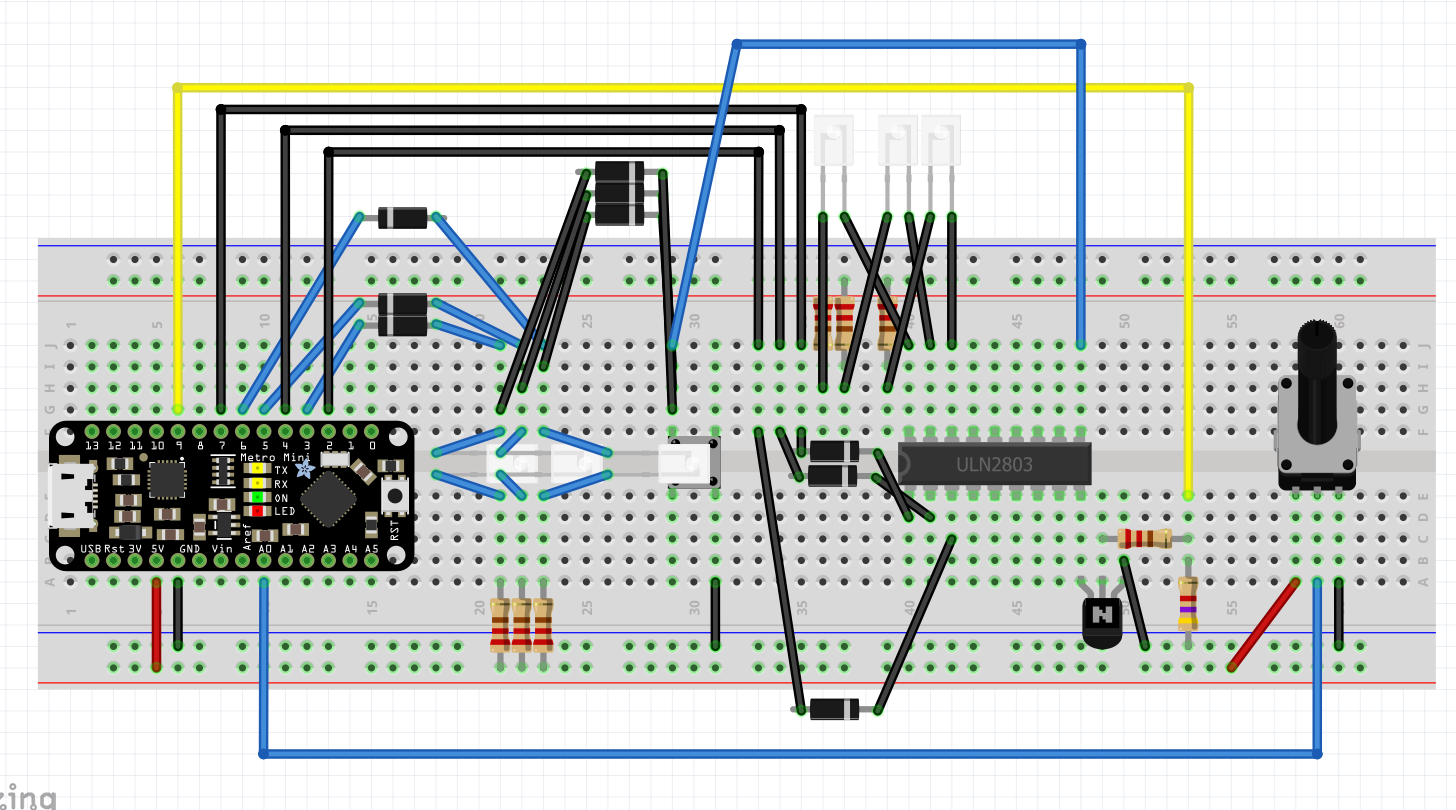
I'm going to spare you a lot of the troubleshooting. Here's the final circuit in fritzing (which I'm not using for PCB design, but is (somewhat) helpful for breadboard illustrations:
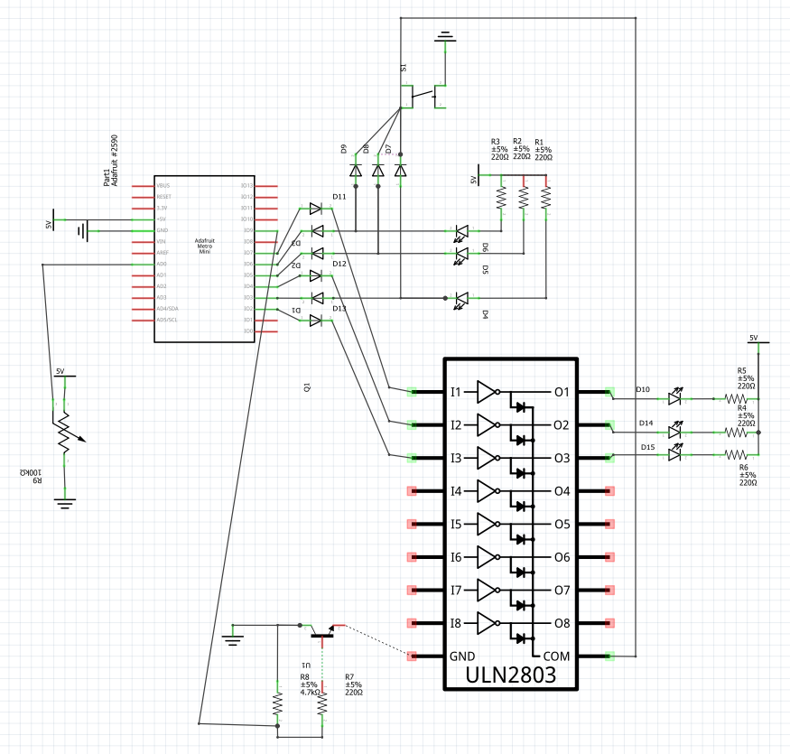
Here's a terrible schematic:
Code can be found here:
https://gist.github.com/mrpeverill/9cb6b14f50befc2daf1d557ecb9a955d
Code is pretty simple. The only complication is that you have to sign flip the PWM signal for one set of LEDs for another. I'm pretty sure I could get around that with a PNP transistor, but I don't have any (edit: yes this totally works!).
Here's a video:
Discussions
Become a Hackaday.io Member
Create an account to leave a comment. Already have an account? Log In.