 Matthew Peverill
So in my new board I wanted to reduce the number of MCP chips used, since those use up board space and board space is $$. If you don't know what a diode matrix is, basically it's a multiplexing strategy (a way to get lots of inputs on fewer pins) and it's been better written up than I possibly could. Here are some resources:
- The best guide on diode input matrices was a post by komar about making a keyboard.
- Hackaday made a post on economic multiplexing strategies.
- arjhun maintains a script to generate a diode keyboard matrix schematic in Kicad.
Guides like these tend to have some interpretation room, however. Notably, I wasn't sure where to put the pull-up resistors. Boards are expensive and you never want to print one unless you know the wiring is right, so here is a breadboard test.
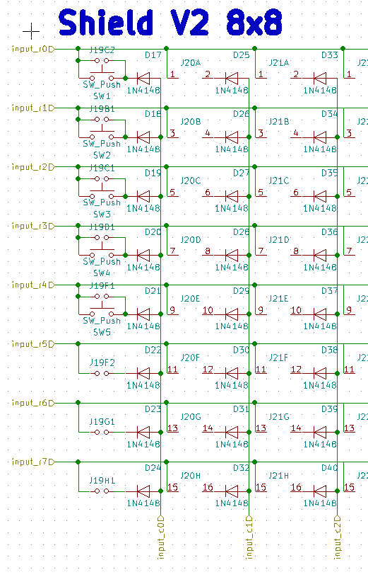
Schematic (from my controller):
pt 1:
And the parent sheet:
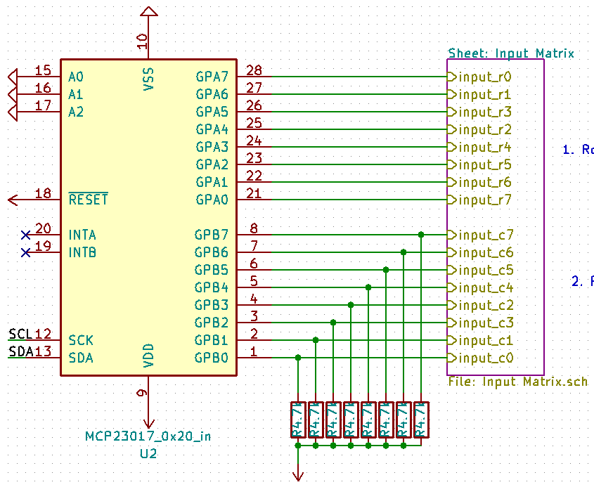
So to translate: Rows are plugged in to GPIOA. We set the row pin to be read to low (the rest to high), then we read the column (GPIOB). GPIOB pins are pulled high.
Here's a breadboard with four microswitches hooked up in a matrix (using my adafruit metro mini):
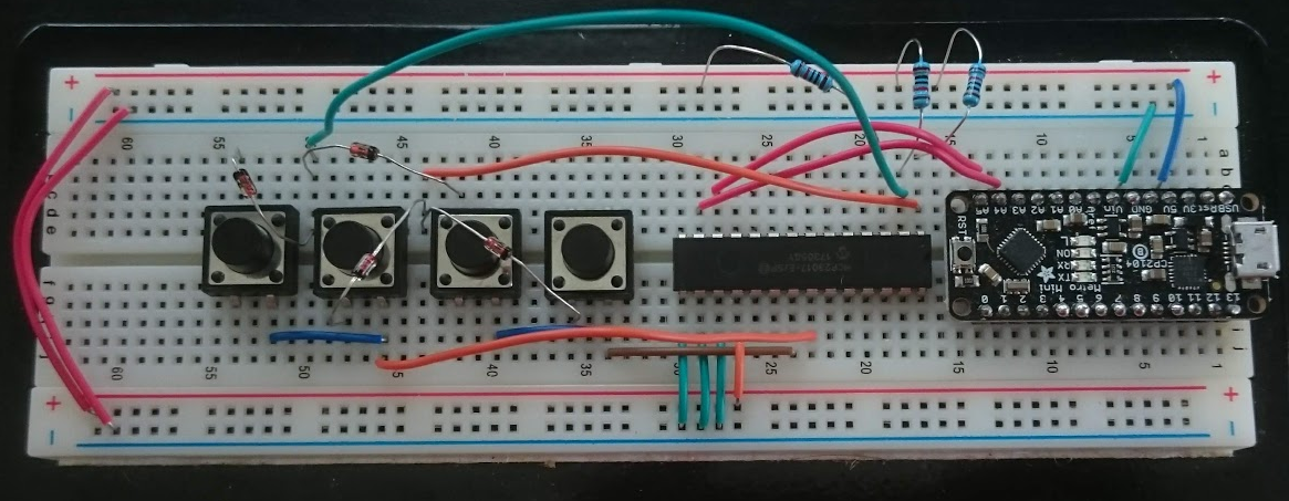
(remember: black stripe goes toward the pointy end in the schematic)
And here is a test sketch:
#include <Wire.h>
  const byte mcp_address=0x20;      // I2C Address of MCP23017 Chip
  const byte IODIRA=0x00;
  const byte GPIOA=0x12;            // Register Address of Port A
  const byte GPIOB=0x13;            // Register Address of Port B
  const byte qrows[] = {0b11111110,0b11111101,0b11111011};

void mux_Tx(int adr, int reg, byte data) {
  /* This function will send data to a MCP23017 chip */
  Wire.beginTransmission(adr);     /* address the chip */
  Wire.write(reg);                 /* point to the register of choice */
  Wire.write(data);                /* send the data */
  Wire.endTransmission();          /* end the transmission */
}

void mux_Rx(int adr, int reg, int numbytes, byte *data) {
  /* This function will request n bytes of data from a MCP23017 chip */
  Wire.beginTransmission(adr);     /* address the chip */
  Wire.write(reg);                 /* point to the register of choice */
  Wire.endTransmission();          /* end the transmission */
  Wire.requestFrom(adr, numbytes); /* request the data */
  *data = Wire.read();
}

void printBin(int var) {
  for (unsigned int test = 0x80; test; test >>= 1) {
    Serial.print(var  & test ? '1' : '0');
  }
}

void setup() {
  Serial.begin(9600); // Initialize the serial port
  Wire.begin();
  mux_Tx(mcp_address, 0x00, 0x00);  /* MUX 0x23, IODIRA, Set all to output (0) */
}

void loop() {
  for (int row = 0; row < 3; row++) {
    byte buff=0;
    mux_Tx(mcp_address,GPIOA,qrows[row]);
    mux_Rx(mcp_address, 0x13,1,&buff);
    printBin(buff);
  }
  Serial.print("\n");
  delay(100);

}
(incidentally, I highly recommend aliasing your MCP23017 registers if you're using them this way).
This outputs three rows. You can see on line 3 where a button was depressed:
000001110000011100000111
000001110000011100000111
000001110000010100000111
000001110000010100000111
000001110000010100000111
000001110000010100000111
000001110000010100000111
000001110000011100000111
000001110000011100000111
000001110000011100000111
It works! Now I can print the board.
Discussions
Become a Hackaday.io Member
Create an account to leave a comment. Already have an account? Log In.