This simple and cheap project in its standard form implements an audio delay using an inexpensive ESP32S NodeMCU board and incorporates an optional VOX to trigger a transmitter with the delayed audio so that said audio is not lost due to VOX response time, key-up delays or CTCSS processing delays at endpoint receivers. It was built for a simple one way cross band rebroadcaster which uses off the shelf portable two way radios, but you could use it in any circuit that needed an audio delay if hi fidelity wasn't a requirement.
I've also included the code for the delay only, (no VOX). This code supports a (practical) audio delay of up to about 12 seconds at a nominal 10k/s sampling rate (depending on typically available heap memory), or proportionately less delay at higher sampling rates (automatic, although I've capped the maximum sample rate at 40k/s).
Why bother?
When I first decided to do this I found there didn’t seem to be much on the internet that dealt with the sort of audio delay I needed; mostly stuff for music echo/reverb effects with fairly ordinary performance using the ubiquitous PT2399 IC hence this RYO approach. The simple ability to add VOX in the same program was a bonus. It is by no means a complex or cutting edge project, just something useful.
Update: I have since found a kit from the Electric Druid that might suit folks who are just after a delay, no vox. see: https://electricdruid.net/diy-digital-delay/
Why use the ESP32?
Because a friend suggested it, because it's cheap, powerful and has an "adequate" ADC and DAC on board along with a decent size memory - and because I could program it using the Arduino IDE instead of having to learn a new language or development process. OK, yes, it doesn't use the wifi, bluetooth etc.. facilities, so again, yes, it's the proverbial sledgehammer cracking a nut.
Status
Status: working in basic form
To do: finish boxing up the working prototype for field trials.
General discussion
Performance of the delay is not bad for voice at a sample rate of 20k/sec, and the original test lashup can get by without any anti-aliasing filter on the input, probably because the audio response on the incoming receiver is too poor to carry much in the way of non-voice frequencies, and the input on the transceiver is likewise not too fussy.
The program allows for extension of the delay up to about 10 seconds at progressively lower sample rates.
Time shift VOX mode
In VOX mode, the input audio stream is continuously stored in a ring buffer. The processor keeps a running average of the input level over a configurable period of samples (0.3 seconds in prototype). If this exceeds a threshold, the VOX is triggered, raising a transmit signal so the radio which sees the delayed audio is immediately set to transmit and the output DAC is enabled thus starting to send recorded audio from a defined delay time before the VOX was triggered (time shift).
The VOX/transmit remains triggered until input audio is stopped and stays triggered for a full delay period plus a small bit extra (the Tail) before turning off the radio transmitter transmit signal.
The idea is to compensate for missing audio due to delays in VOX triggering. By transmitting a bit of silence before the payload audio, you can also compensate for slow key-up of the transmitter and slow triggering of the eventual receiver.
The unit can be used with transceivers that don't have a separate transmit line but do have their own internal VOX.
I have also added the ability to insert a beep at the start of the delayed output audio.
The VOX as implemented...
Read more »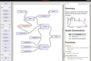
 Paul Stoffregen
 ClockLoop
 Raymond Lutz
 Guido
Guido