This project has been sponsored by LCSC.com. LCSC has a strong commitment to offering a wide selection of genuine, high-quality electronic components at best price. LCSC has become the fastest developing online store of electronic components in China.
A quiz is an important event in any school/College institution to test the knowledge of the participants. In order to increase the difficulty, the spontaneity of the participants is also tested in which the reaction time of the participants also matters. So, to indicate the person who is ready first to answer the question has to push the buzzer. It is also hard for a judge or the organizer to identify the first person who pushed the buzzer ON, since the participants race to answer the question. So Here we have added one feature in which if someone presses the buzzer first then all the remaining participant‘s buzzer gets disabled and the buzzer will not sound again until the reset button is pressed.
There are 3 popular configurations of 555 timer IC:
These configurations have a difference in the number of stable states. Here in this project, we will use a bistable multivibrator mode of 555 timer IC. It will have two stable states. First, when the participant presses the button and the second is when the buttons are reset by the quiz host.
Things you will need
- 3 x 555 Timer
- 3 x Tactile Switch
- 1 x BC547 Transistor
- 1 x Buzzer
- 3 x Red LED
- 3 x Green LED
- 1 x 1N4007 Diode
- 4 x 10k Ohm Resistor
- 3 x 1k Ohm Resistor
- 1 x Breadboard
Going further...
We have used three 555 timer ICs in a bistable configuration. The important part is each 555 IC will have their own stable state which is controlled by separate buttons to be accessed by the participants. There is another single button which controls the other stable state of all the timer ICs in common which is accessed by the host/judge of the quiz. This button will reset the entire circuit. When any of the buttons S1, S2 or S3 is pressed, the corresponding TRIGGER pin gets low and the corresponding timer goes high. And the LED of the corresponding participant turns on and buzzer starts beeping.
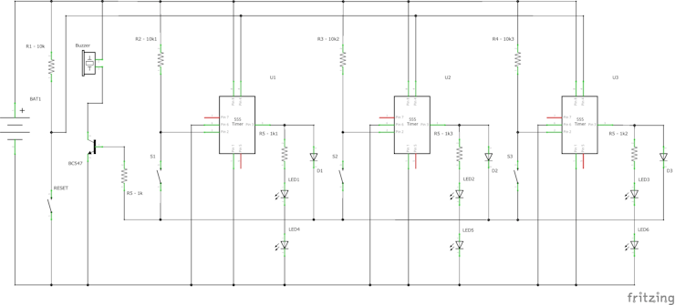
The operation is that when the first stable state of anyone timer is set, it disables the remaining timers. This is because the forward biased diode connected to the output pin of the set timers gets forward biased making the remaining button terminals go high. Hence, even if the other buttons are pressed after this, the corresponding timer's pin sees the only high signal. Hence, the buttons work only after resetting the entire circuit. The buzzer is controlled using NPN transistor BC547 whose control signal is the common TRIGGER to which buttons are connected. Also, the buttons are grounded through an internal diode of the transistor.
Working of the circuit
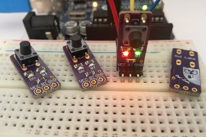
The whole circuit can be powered by 5V or 9V battery. Initially, the circuit is in RESET condition and waiting for the TRIGGER signal. So, as soon as the participant presses the button, the corresponding timer changes its state and output go high and the buzzer sounds to indicate the button press.

Above image indicates that the button S1 is pressed and the remaining buttons will be disabled.
Now when the RESET button ORG is pressed the circuit goes to initial state and again waits for the next TRIGGER.
The RED LED is to indicate the organizer about the first person to press the button.
 1 / 2 • Second participant presses first and other buttons gets deactivated....
 Alain Mauer
 Steph
Steph
 Owl Labs