 David Troetschel
The previous case was far from attractive, so hopefully this looks better and functions better as well.
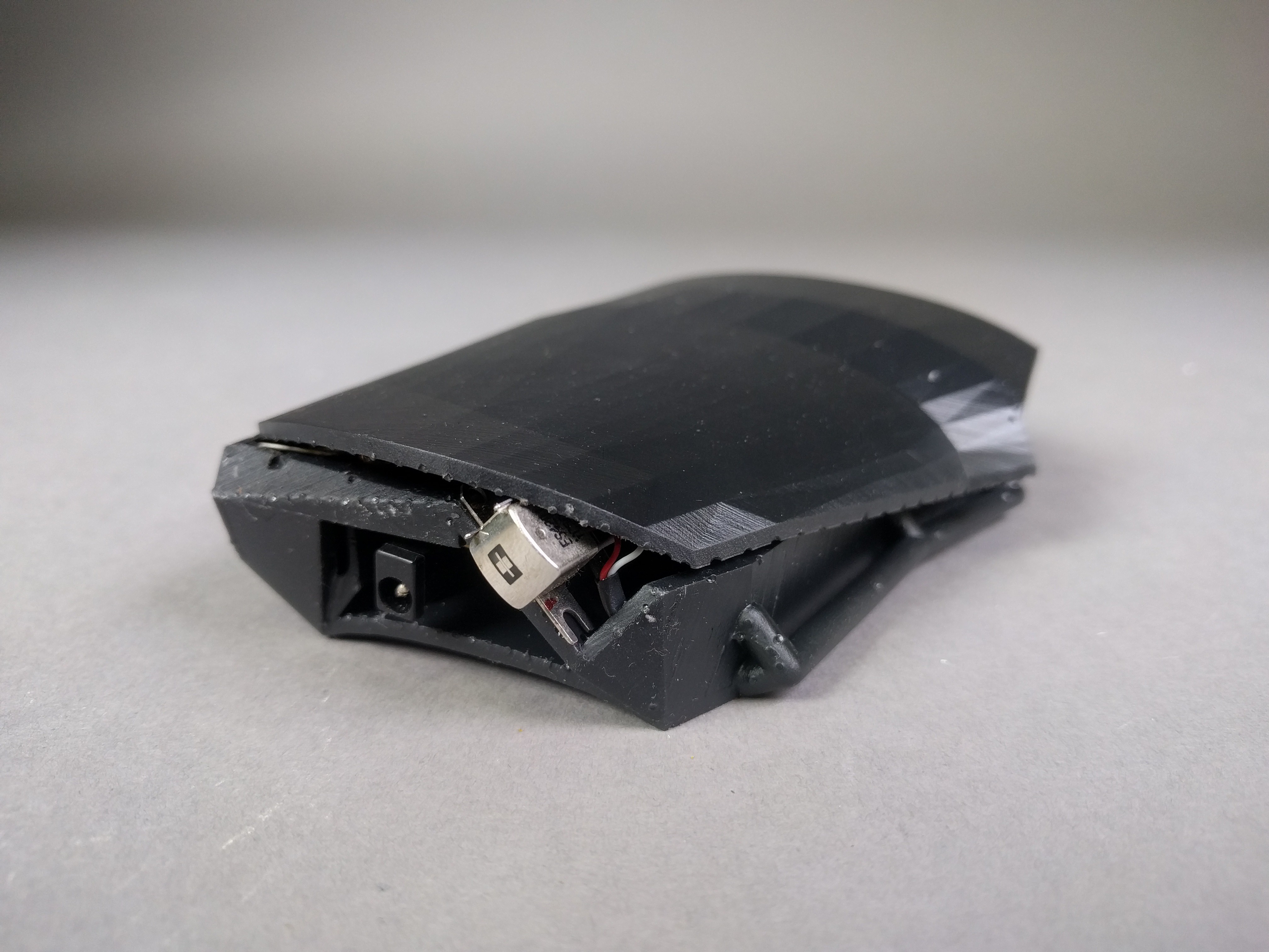
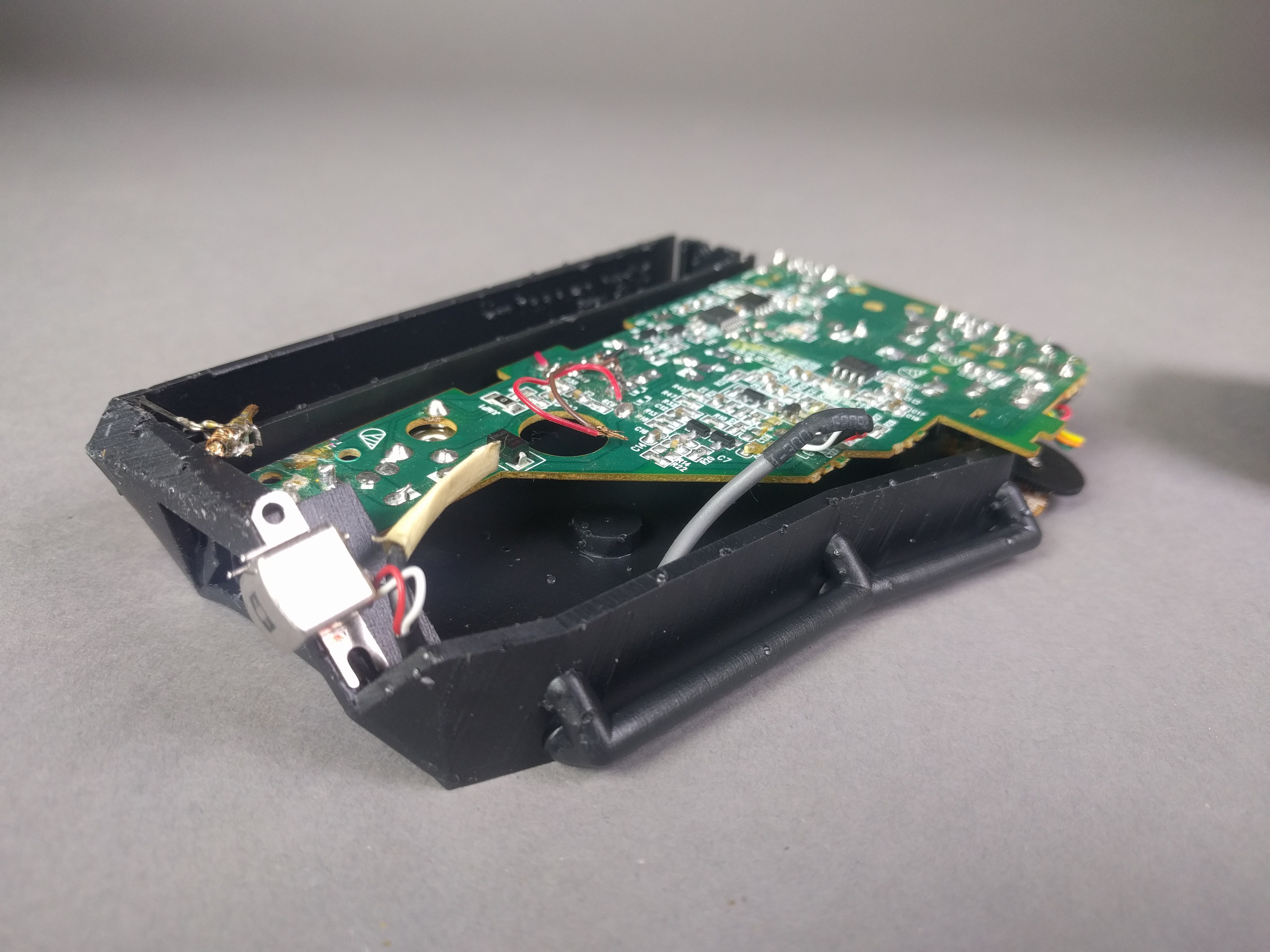
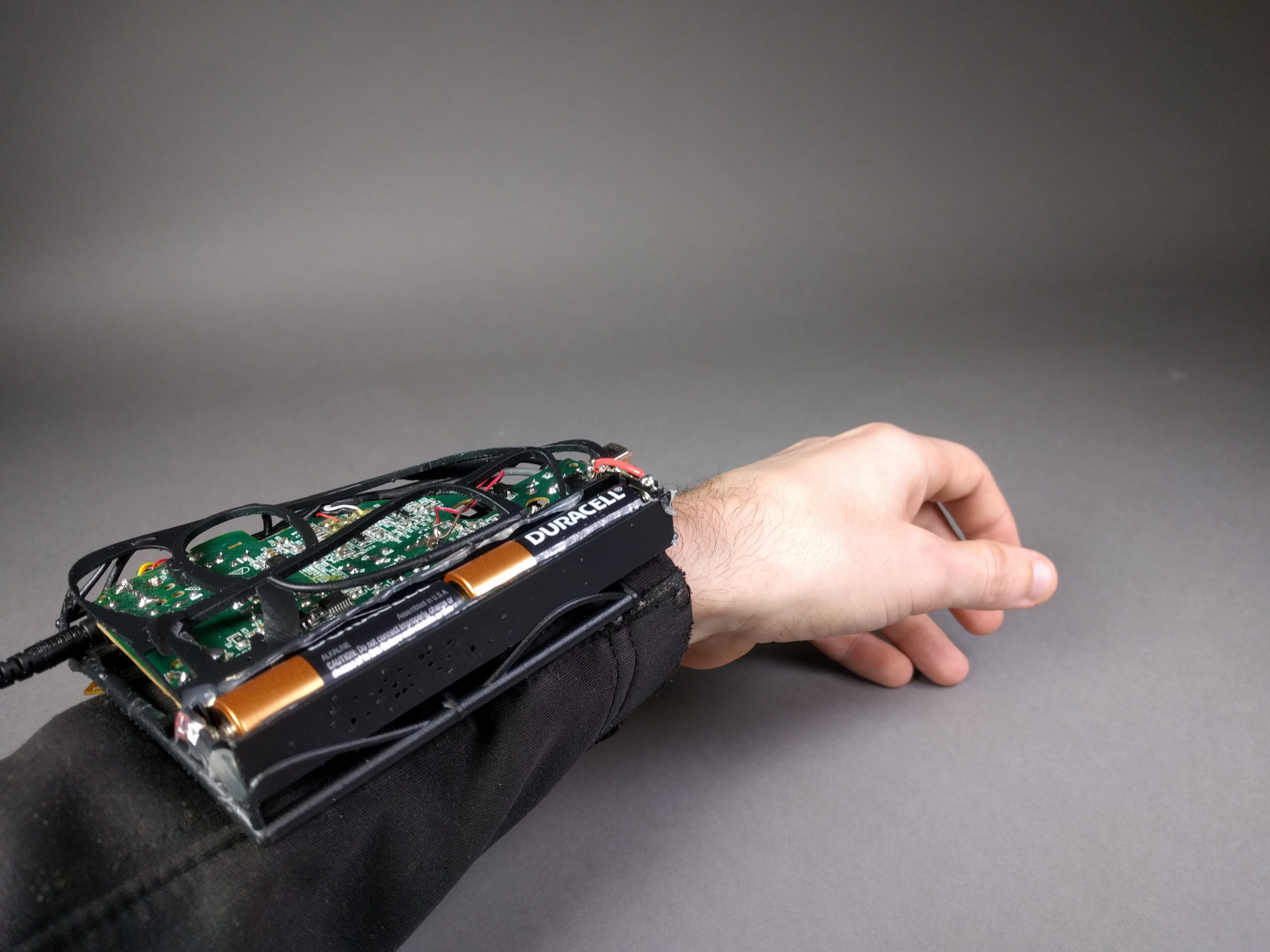
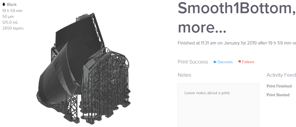
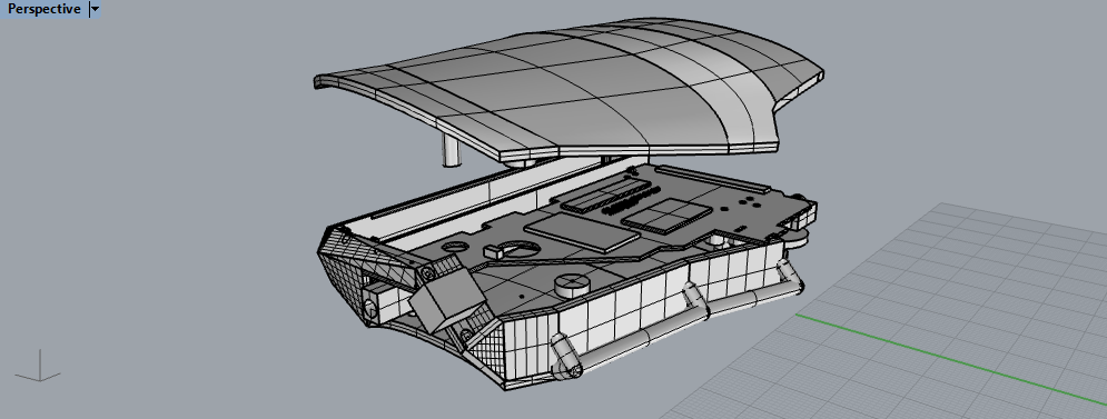
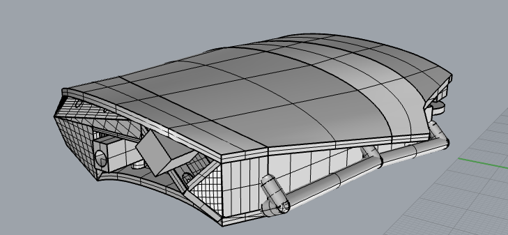
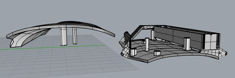
The case should look decent and will be 3D printed. My goal is for it to be showy enough that it doesn't freak people out and offers ample room for modifications. Controls should be easily accessed and it should be a wearable with the exposure window facing towards the hand. This should not draw too much attention but an "exhibition mode" is desired (a loud speaker.)
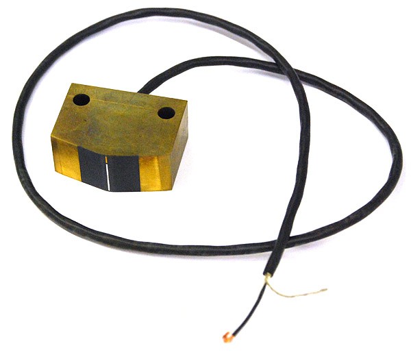
In the end all you should need is access to a decent printer, a cassette player (or the plain magnetic read heads and relevant circuit board), some soldering skills if you feel like cleaning up the wiring harness, velcro straps or elastic straps and maybe a rechargeable battery in a future design.
Feedback is more than welcome.
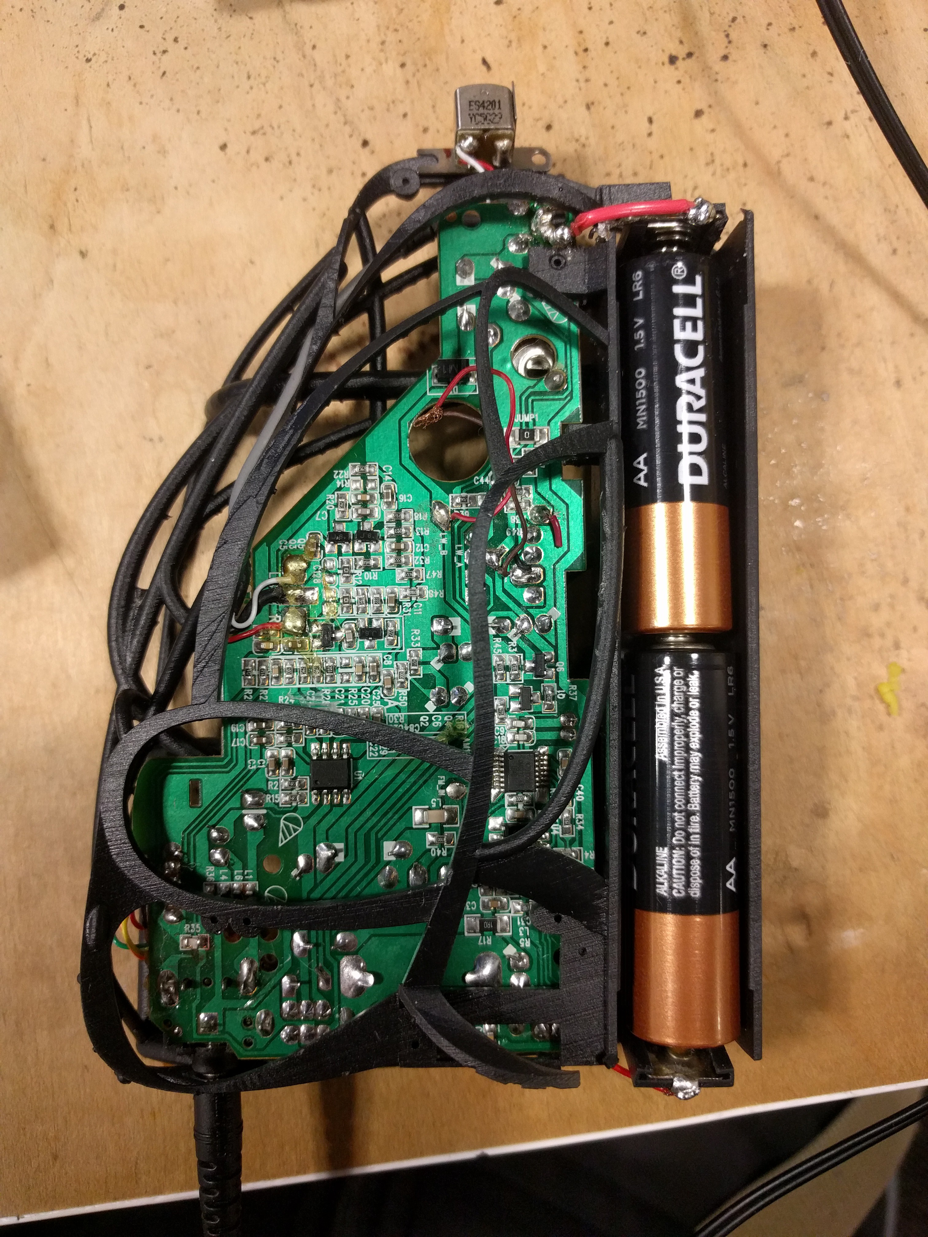
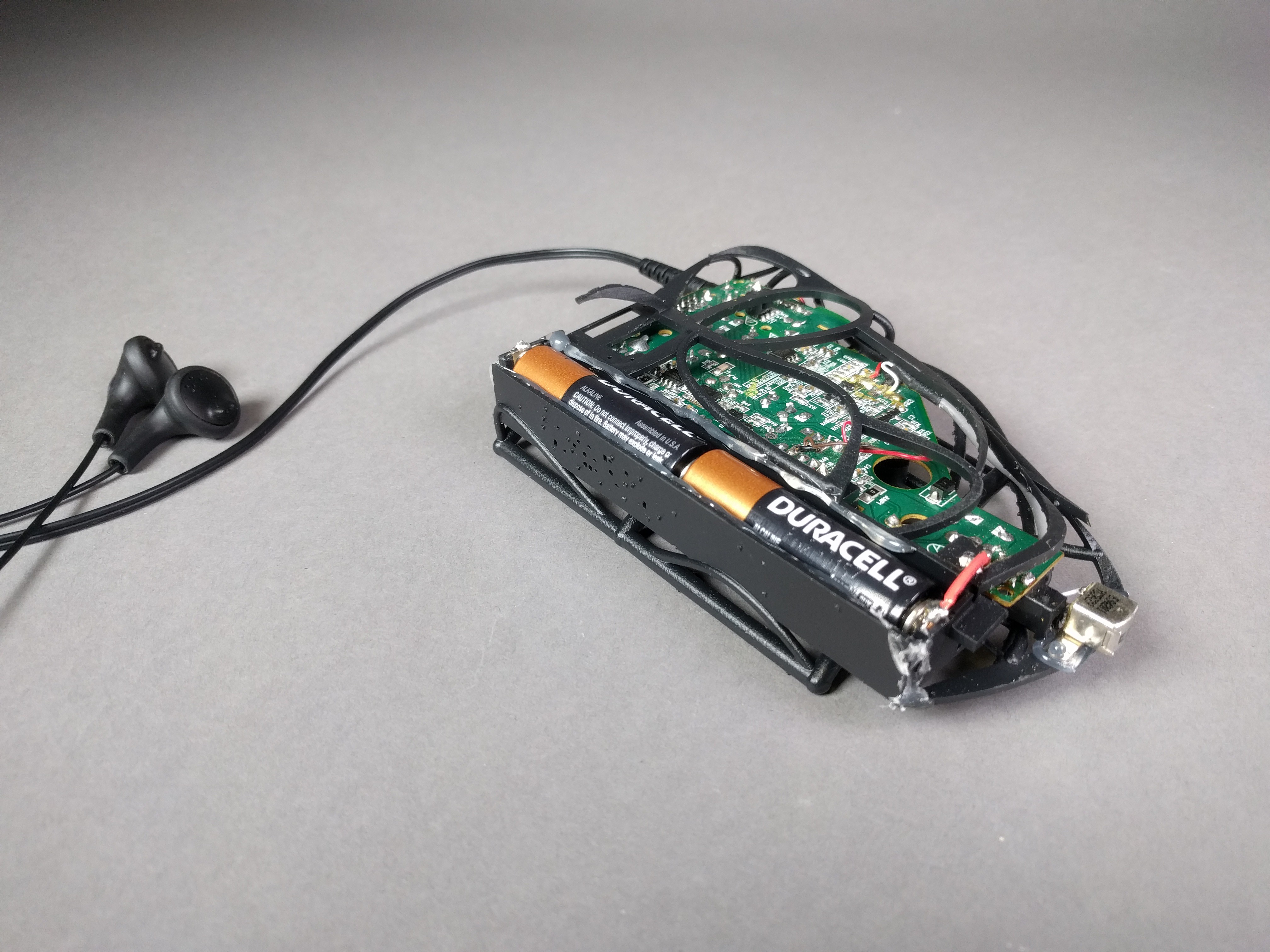
Below is the first production prototype:
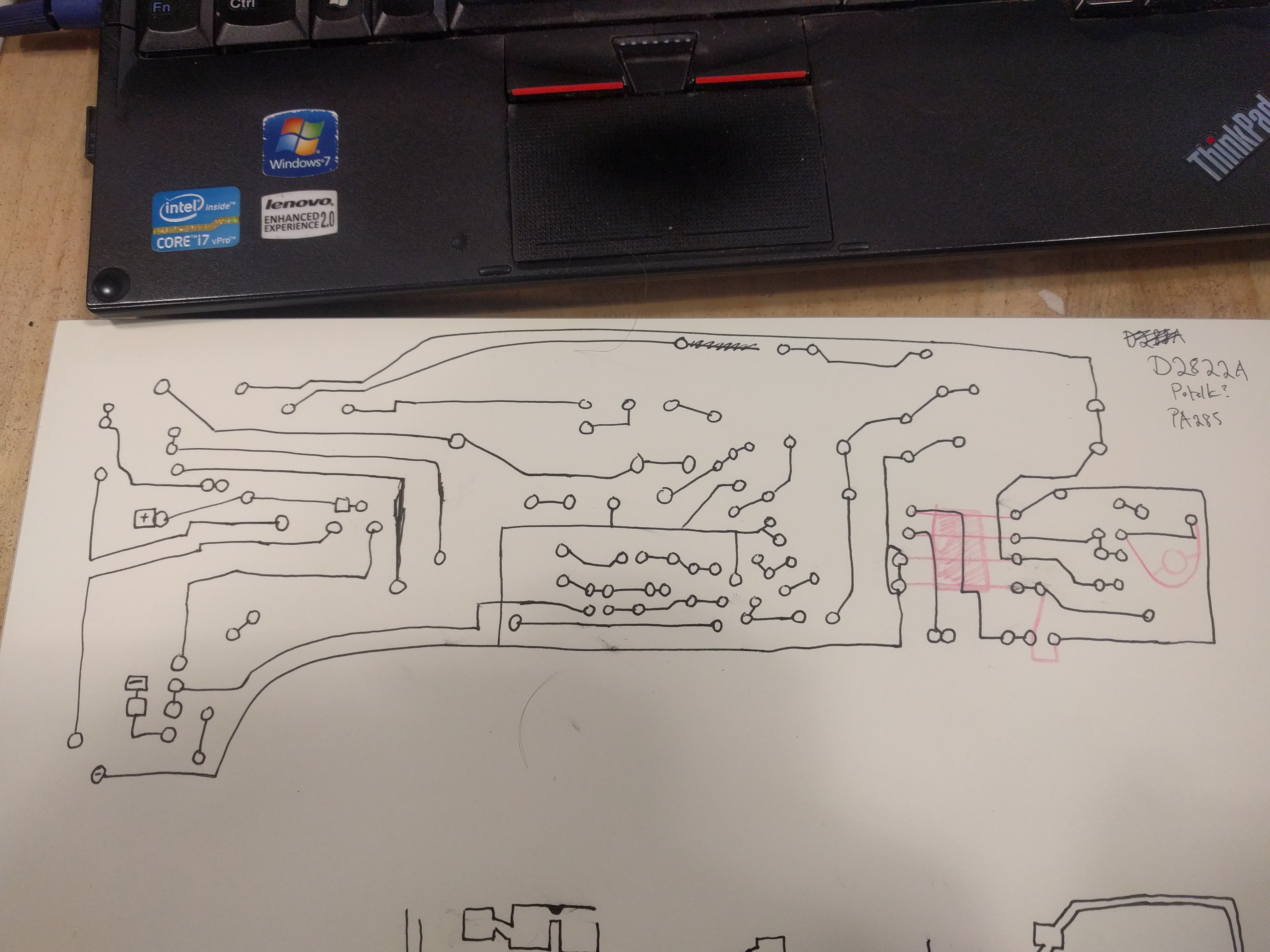
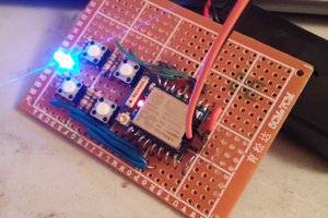
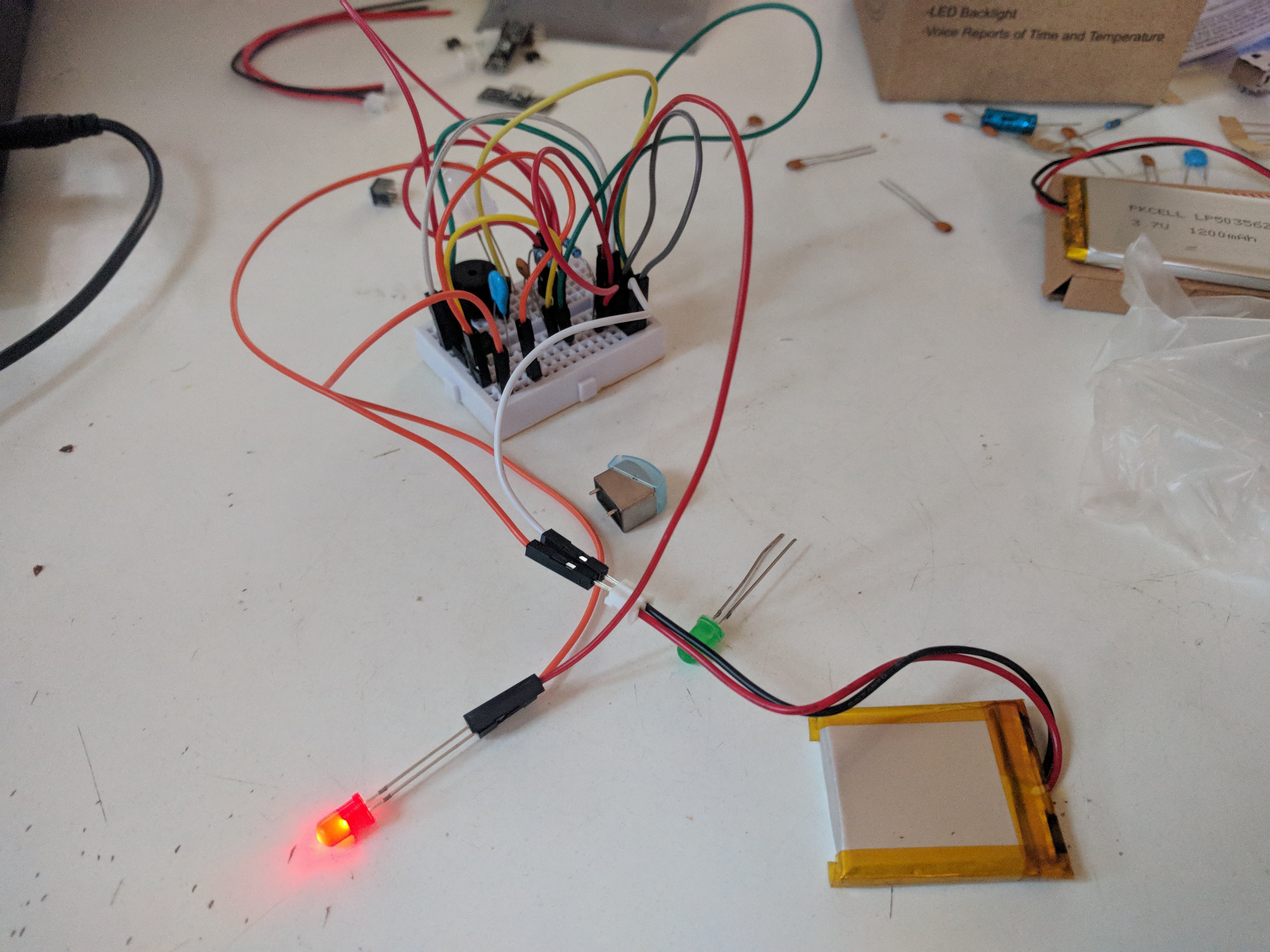 I've been testing some circuits with a little success.


 K Gilbert
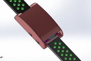
 Chaz
Chaz
 Anthony
 Jean Simonet
You could reverse engineer a ghost meter to see how it's done.
Another way to detect a specific frequency would be to design something around a transceiver chip. Check out https://www.analog.com/en/design-center/reference-designs/hardware-reference-design/circuits-from-the-lab/cn0360.html
it's a circuit to detect a band from 35 MHz to 4.4 GHz. Analog Devices has several tutorials about detecting various frequencies and they have some (unfortunately > $100) dev boards that work off the shelf for experimentation.