 Deepak Khatri
The circuit is very simple only one transistor is needed and the brightness of the LED is wow!!!! with only 1.5V it will lit the RED LED on its full brightness (You can try other color if you want to).
0%
0%
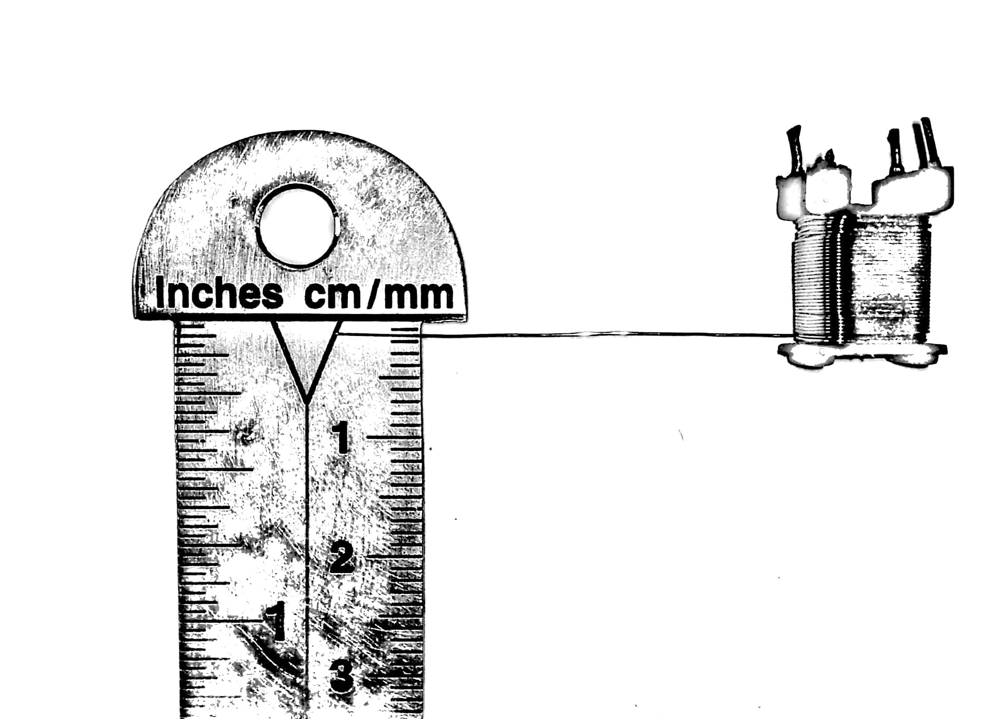
Resonance Induction - Wireless Energy Transfer
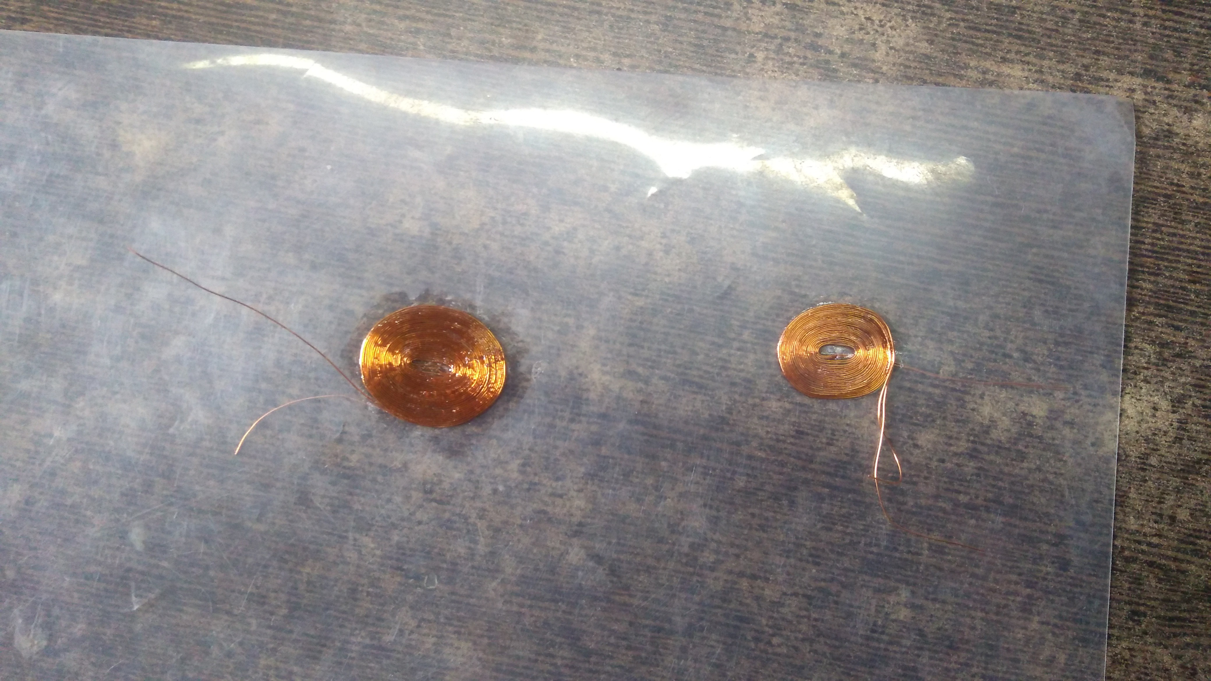
DIY flat coils and wireless energy transfer circuit project, that works like a joule thief but with wireless capabilities!!
Become a Hackaday.io member
Already have an account? Log in.
Just one more thing
To make the experience fit your profile, pick a username and tell us what interests you.
Pick an awesome username
hackaday.io/
Your profile's URL: hackaday.io/username. Max 25 alphanumeric characters.
Pick a few interests
Projects that share your interests
People that share your interests


 BetaMachine
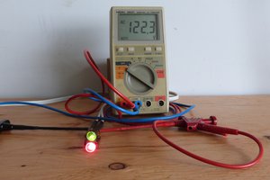
 MagicWolfi
 Electroniclovers123
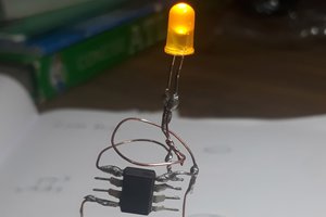
 Amal Mathew
This is really very cool, but what would need to change to pass 7.4v ?