 Yann Guidon / YGDES
So one day my neighbour comes and asks for help. Why not ?
Imagine you play chess against your opponent. Sometimes one of your pieces falls into a trap that opens suddenly as you press the button of the timer.
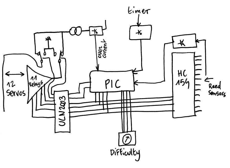
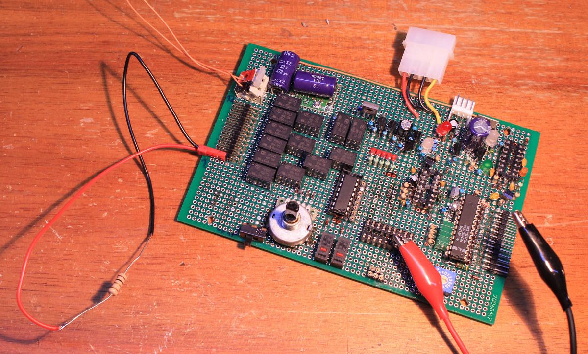
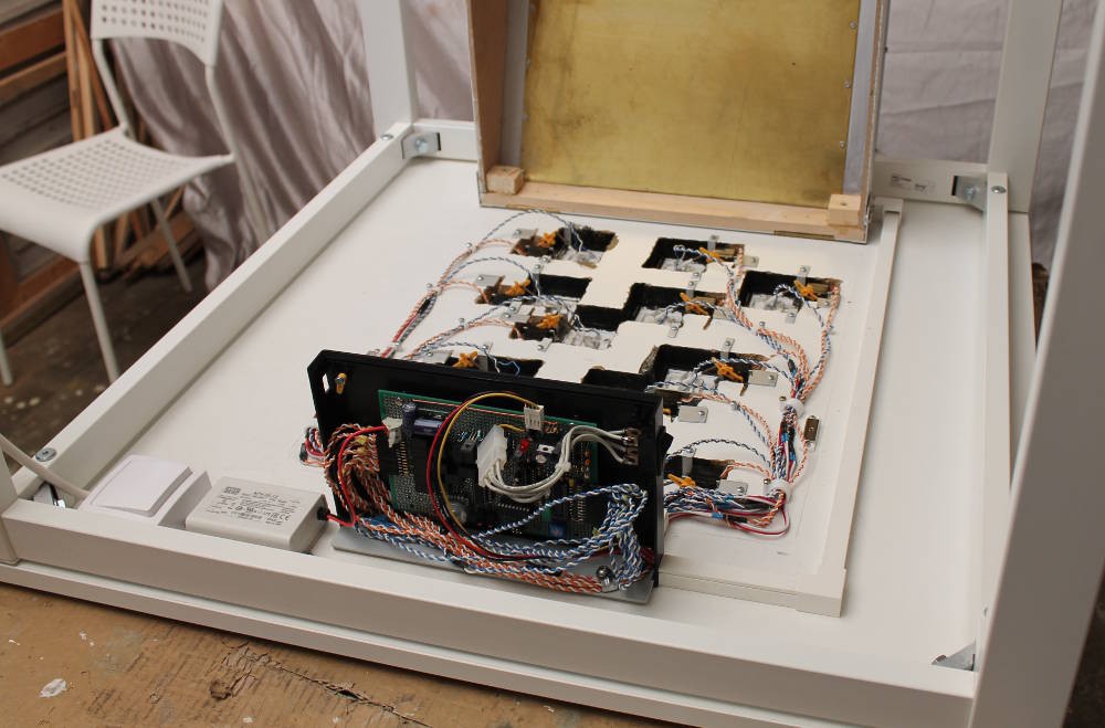
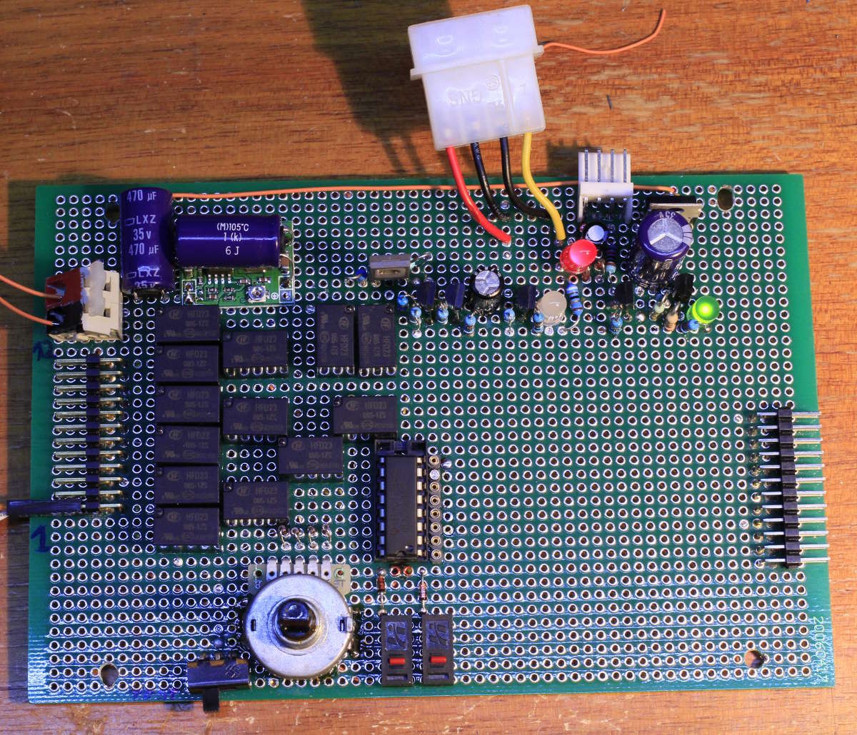
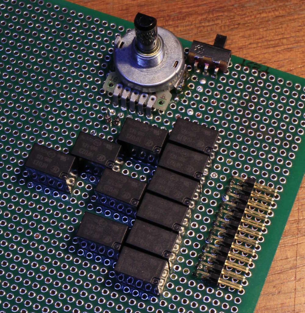
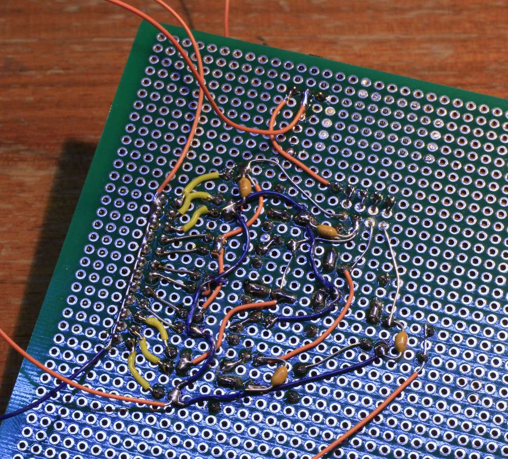
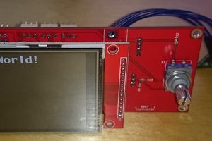
Bob has built two chess boards with traps, operated by individual servomotors. Each chess pieces has a magnet, that is detected by reed sensors. My mission is to create the electronic board to control the whole thing... Uncontrollably.
Logs:
1. Timing
2. Plot twist !!!
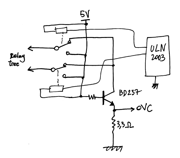
3. Power distribution
4. More work
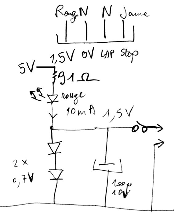
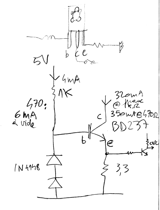
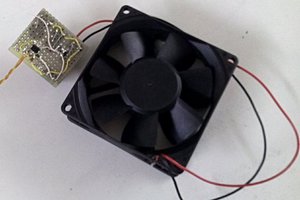
5. a not-so-basic current sensor
6. Connecting the timer
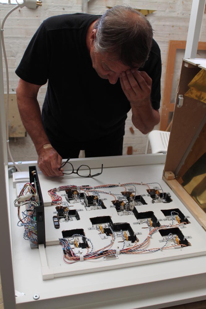
7. first tests with the checkerboard
8. More progress
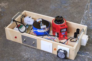
9. Power Supply redesign (20190331)
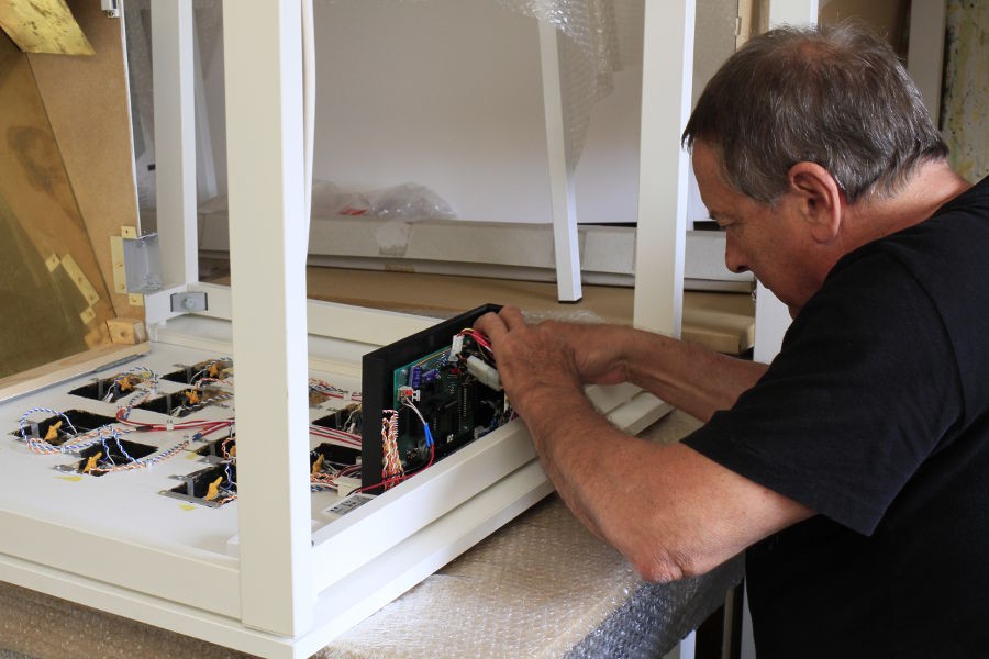
10. First prototype working !
11. Finished
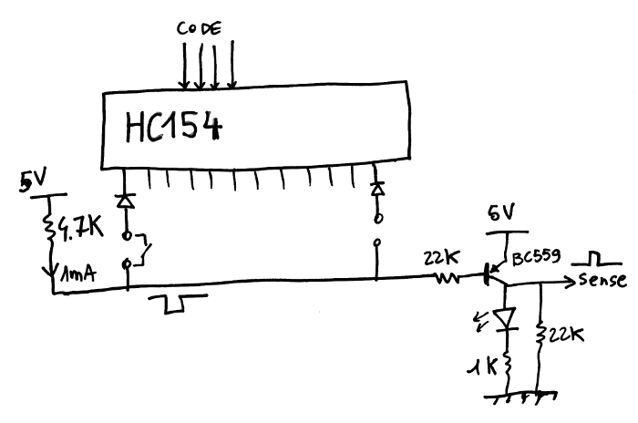
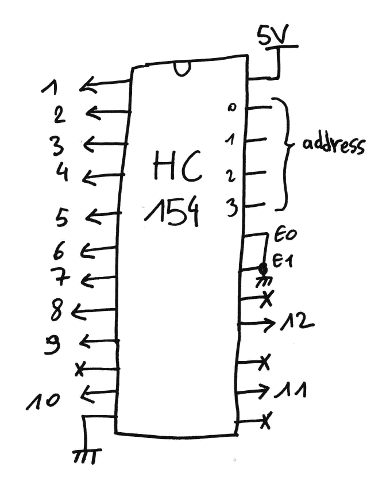
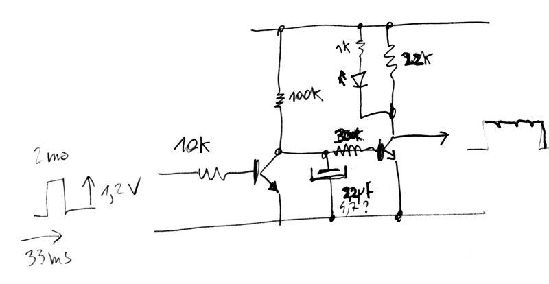
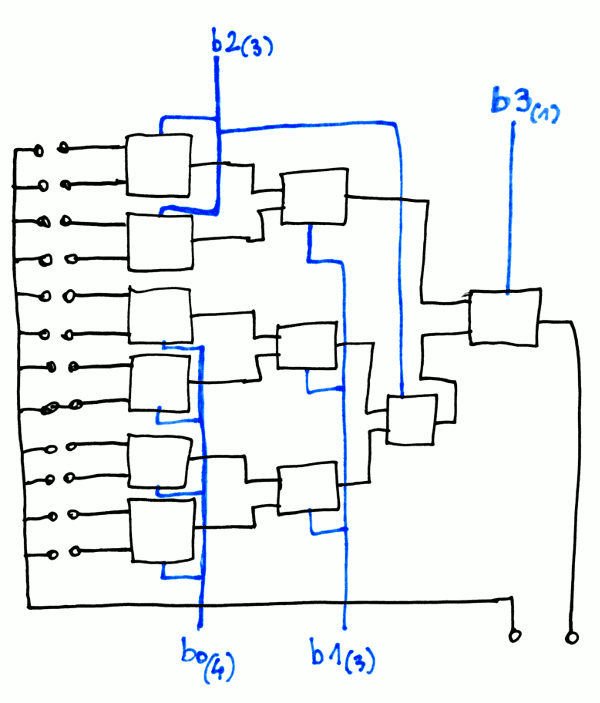
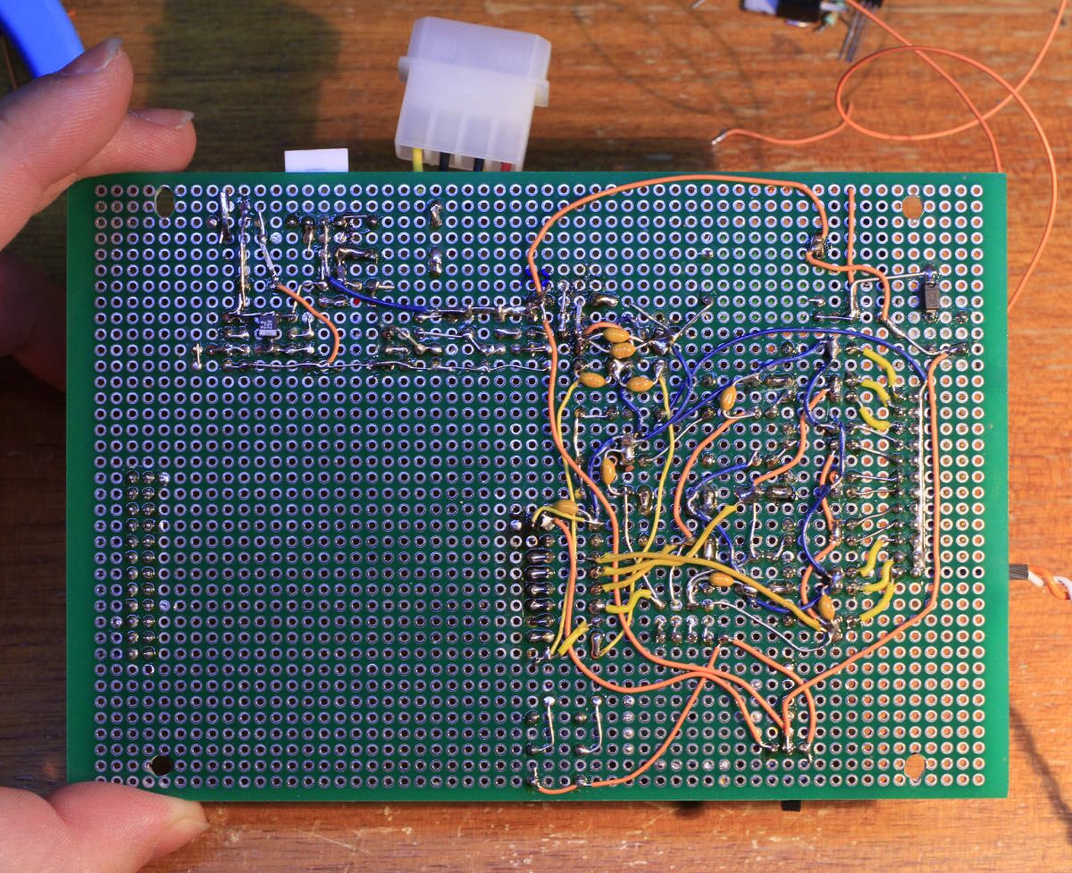
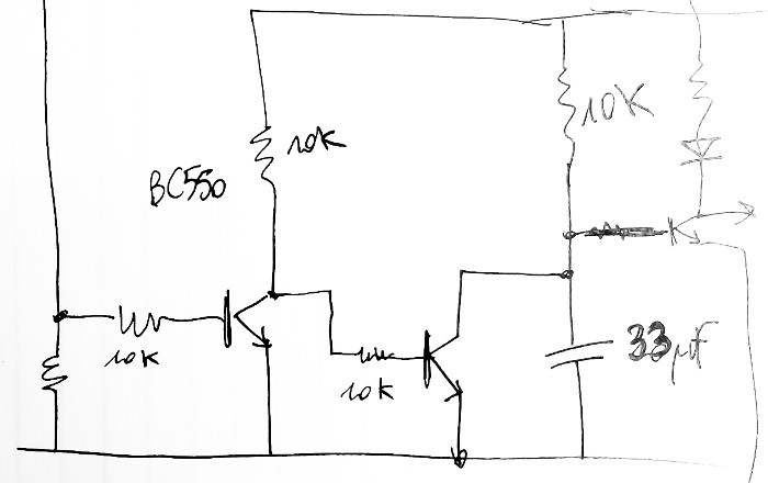
12. Some schematics


 SUF
SUF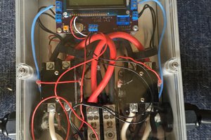
 Nick Sayer
Haha, that's great! Chess...with the element of surprise! Good effort on attempting to do it all in discrete logic...guess we can't give up our micro's just yet!