 Yann Guidon / YGDES
I finally decided to use relays to distribute the power to one selected servo.
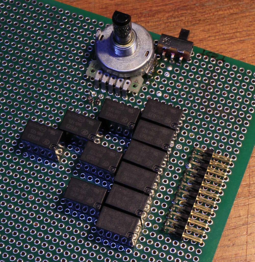
The path of the power goes through an unbalanced binary tree, made of parallel 8-tree and 4-tree, with a control vector of [1, 2, 4, 4] (total is 11, which is 12-1 as expected).
The relays have a 160 ohms coil, or 32mA @ 5V. The driving requirements for the tree are 32, 64, 128, 128 mA. This is well within the range of a ULN2003 and the total draw (worst case) is about 0.35A.
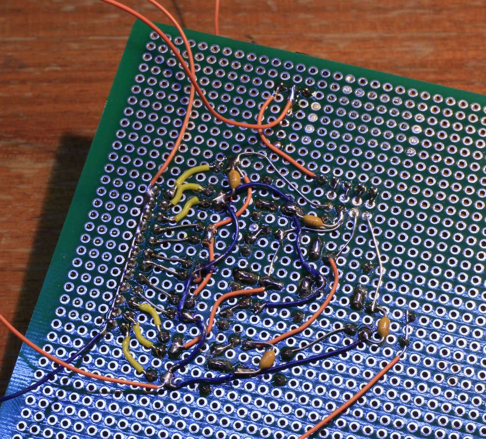
The reverse side is the usual mess:
The 16-positions knob selects one of the 12 outputs, 4 outputs have a duplicate code. I can test the behaviour by hand and the manual control is really helpful during prototyping and later for installation and troubleshooting.
The hex encoder must be disabled during normal operation, which is selected by a small slider switch. This requires anti-feedback diodes on the knob's inputs, hence an increase of the power voltage.
Oh and of course, there is a lot of work to do because now, the servo's motor must be wired directly (the control PCB must be removed). But for now I must focus on controlling the current's direction and detecting the increase of current when the servo has reached its limits. Hint: a 3.3 Ohm resistor develops a potential less than 0.7V when the servo operates normally.
Discussions
Become a Hackaday.io Member
Create an account to leave a comment. Already have an account? Log In.
I like it when the physical circuit looks like the schematic! (at least on the component side :-)
Are you sure? yes | no
yeah, it's a limited series (2 units) so the board is also the prototype... There is no point in over-optimising it, it has to work cheap and soon :-D
Are you sure? yes | no