 Yann Guidon / YGDES
I just gathered, and even re-sketched, the major schematics for the electronic circuits of the controller. I believe it's important because I made a very bad mess with the wires, throwing all the convention out of the window (don't look for colour consistency).
Let's start with the general overview.
There are inputs, outputs, some power and a controller.
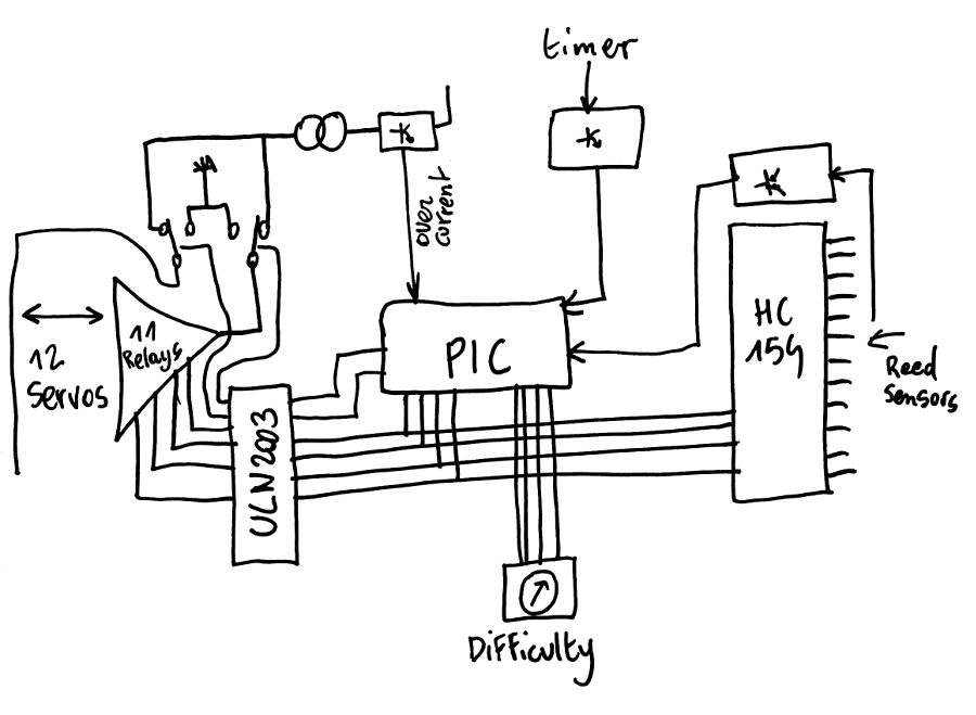
There is nothing really crazy here, just notice that the channel number is shared with the input selector and the output driver. This creates the typical "click" sound that everybody loves, when tapping the timer. It's not a bug, it's a feature ;-)
The power system is split into 3 parts and all the energy comes from a dumb 12V source, at most a fraction of ampere. Quiescent current is about 20-25mA but it jumps when the relays and the motors are driven.
A dumb 7805 powers the digital circuits (PIC and HC154), and a DC/DC module can drive about 1A max. to the relays and the servos (through a current limiter).

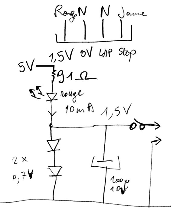
The external timer is powered from the 5V rail and draws some significant current : about 10mA with a really nasty shunt regulator. The timer draws very little current, yet the regulation takes about 10mA (tested from 4V to 6V). This keeps the 7805 "in regulation". A dumb diskette power connector connects to the timer, also bringing some input signals.
The PIC gathers all the signals and distributes the control lines. Nothing significant here, apart from the custom ICD connector.

The presence of a chess piece is detected when one of the magnetic reed sensors closes. Each location is sequentially selected by a 74HC154 which pulls one of the outputs to 0V.
A pull-up (4.7K) pulls a common rail/signal to 5V so when one of the reed contacts closes, the selected line pulls the rail down to a a diode drop (in case several sensors are closed simultaneously). This signal is then inverted and buffered by a PNP inverter.
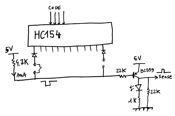
Not shown is an additional NPN inverter connected to the PIC.
As we'll see later, not all the outputs are used : 12 out of 16 codes are valid, the others are just ignored.
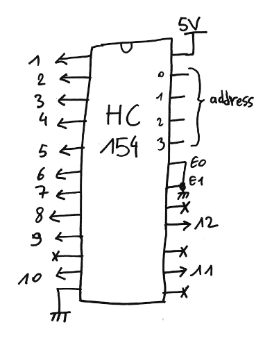
The mapping is determined by the relay tree, see later.
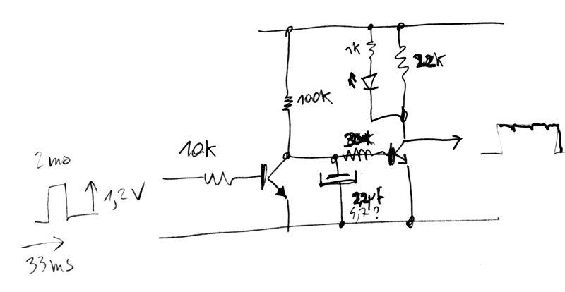
Another input comes from the timer.
A reed sensor is polled by the integrated chip: I measured 2ms-long pulses spaced by 33ms. The pulse is only 1.2V but strong enough to drive a BC550 through 10K at the base.
A pair of NPN inverters buffer the signal and filter the pulse (RC constant given by 2.2µF and 100K).
Not shown : an additional inverter to the PIC.
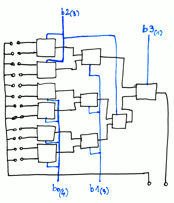
The output servo is selected by a tree of relays, that make this exquisite click sound.
This is an unbalanced binary tree where I tried to avoid excessive driving currents to control all the coils of the leaf relays. I get a (1,3,3,4) fanout and the 4 upper codes (9, 10, 11 & 12) are duplicated and evenly spread over the binary codes 8-15.
There is only one signal to propagate through the tree, the return signal is shared among all the servos.
The current for the servos comes from a current generator followed by a polarity selector, which doubles as on/off switch: 2 control signals drive a pair of relays to provide off, forward, backwards, and off (by design, there is no risk of short circuit).
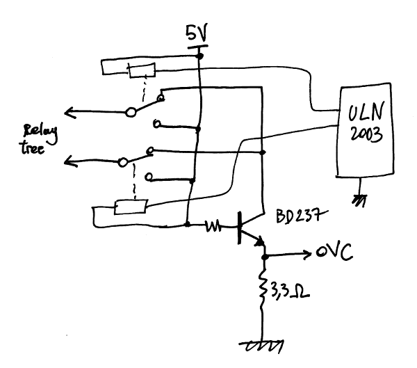
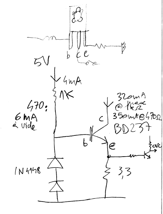
The current limiter is a dumb circuit with a medium power NPN transistor, with the base driven by a chosen current through a simple resistor. There was no point in making a 2-NPN current generator because the drop would not be acceptable. There is some quiescent current (about 6mA) that keeps the DC/DC switch converter loaded.
The emitter is degenerated by a 3.3 Ohm current sense resistor, and the base is shifted by a pair of diodes. The current should be limited to 350mA but no precision is required, as long as it's above the overcurrent sensor threshold value.
The OVC detection circuit looks like the others, with a cascade of NPN inverters.
One of them integrates the signal for some milliseconds because closing the relays creates short pulses that would falsely indicate the end of course. As a previous log mentioned, after I measured the spikes on the 'scope, I managed to calculate the appropriate RC values.
On board#2, I added another inverter that messes a bit with the LED but without severe consequences.
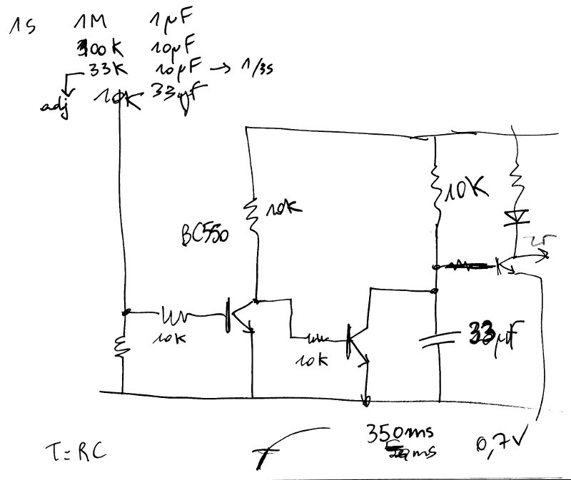
The circuit should trigger when the current exceeds about 200mA (?) because 3.3×.02=0.66V, which is the threshold voltage for the NPN's base. The next inverter then reshapes the signal and short-circuits the capacitor.
In practice, there might be some small variations but at least the principle is quite simple. I used a lot of "tricks" I learned and explored these last years, including my extensive use of BC550 and BC559 ;-)
I decided early against using too much programming and code, this makes the electronics a bit more complex but it's overall more reliable and still easy to repair. The software has relatively little to do and barely cares about the hardware (I added the timeout code later yet it works like a charm).
I'm sure others would have used another approach, more "modern" with an Arduino MEGA with many pins to save on the HC154, or driving the servos with a more classic method. The relays might have a limited lifespan as well... But keeping 12 standard servos powered constantly would draw a LOT of current and 80% of the parts are easy to replace. Most importantly: the clicks add a very fun/stressful sound feedback that the players will both love and dread :-)
Discussions
Become a Hackaday.io Member
Create an account to leave a comment. Already have an account? Log In.