-
Some schematics
09/12/2019 at 02:58 • 0 commentsI just gathered, and even re-sketched, the major schematics for the electronic circuits of the controller. I believe it's important because I made a very bad mess with the wires, throwing all the convention out of the window (don't look for colour consistency).
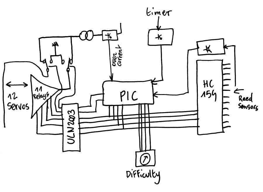
Let's start with the general overview.
There are inputs, outputs, some power and a controller.
![]()
There is nothing really crazy here, just notice that the channel number is shared with the input selector and the output driver. This creates the typical "click" sound that everybody loves, when tapping the timer. It's not a bug, it's a feature ;-)
The power system is split into 3 parts and all the energy comes from a dumb 12V source, at most a fraction of ampere. Quiescent current is about 20-25mA but it jumps when the relays and the motors are driven.
A dumb 7805 powers the digital circuits (PIC and HC154), and a DC/DC module can drive about 1A max. to the relays and the servos (through a current limiter).
![]()
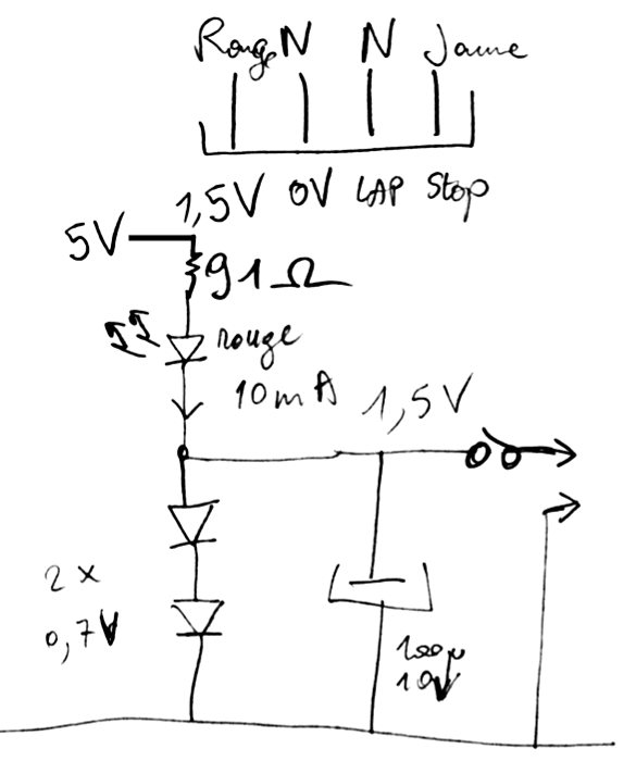
The external timer is powered from the 5V rail and draws some significant current : about 10mA with a really nasty shunt regulator. The timer draws very little current, yet the regulation takes about 10mA (tested from 4V to 6V). This keeps the 7805 "in regulation". A dumb diskette power connector connects to the timer, also bringing some input signals.![]()
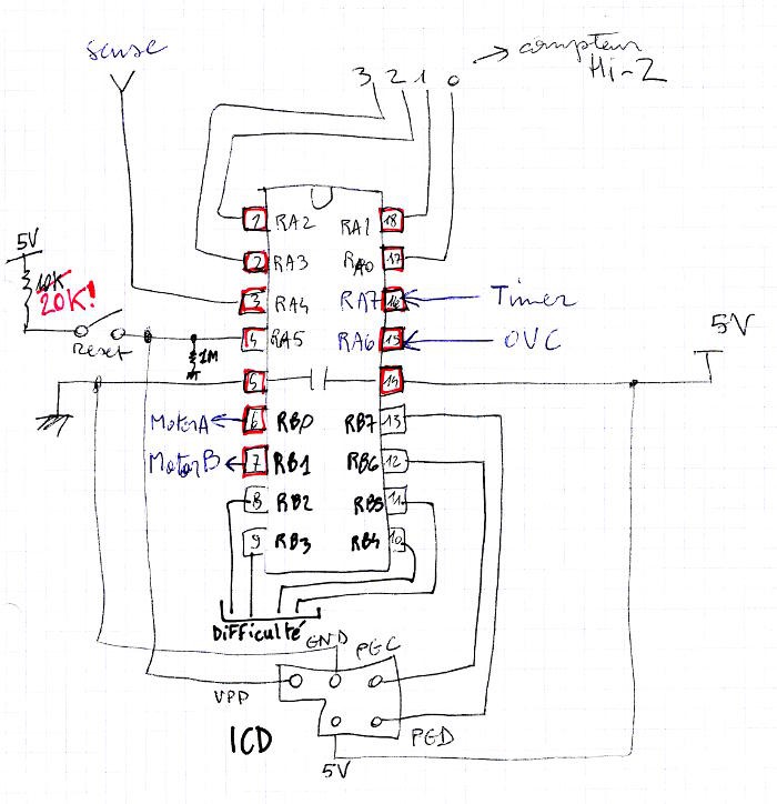
The PIC gathers all the signals and distributes the control lines. Nothing significant here, apart from the custom ICD connector.
![]()
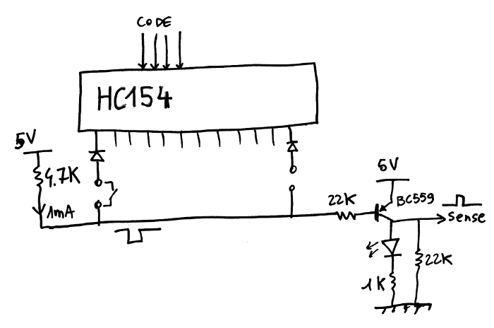
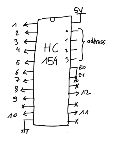
The presence of a chess piece is detected when one of the magnetic reed sensors closes. Each location is sequentially selected by a 74HC154 which pulls one of the outputs to 0V.
A pull-up (4.7K) pulls a common rail/signal to 5V so when one of the reed contacts closes, the selected line pulls the rail down to a a diode drop (in case several sensors are closed simultaneously). This signal is then inverted and buffered by a PNP inverter.
![]()
Not shown is an additional NPN inverter connected to the PIC.
As we'll see later, not all the outputs are used : 12 out of 16 codes are valid, the others are just ignored.
![]()
The mapping is determined by the relay tree, see later.
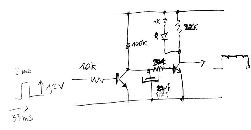
Another input comes from the timer.A reed sensor is polled by the integrated chip: I measured 2ms-long pulses spaced by 33ms. The pulse is only 1.2V but strong enough to drive a BC550 through 10K at the base.
A pair of NPN inverters buffer the signal and filter the pulse (RC constant given by 2.2µF and 100K).
Not shown : an additional inverter to the PIC.![]()
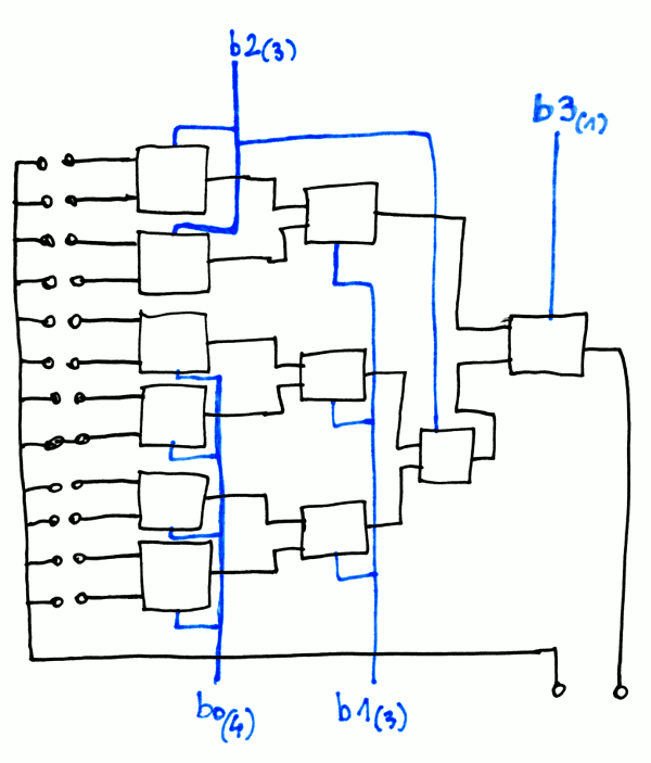
The output servo is selected by a tree of relays, that make this exquisite click sound.This is an unbalanced binary tree where I tried to avoid excessive driving currents to control all the coils of the leaf relays. I get a (1,3,3,4) fanout and the 4 upper codes (9, 10, 11 & 12) are duplicated and evenly spread over the binary codes 8-15.
There is only one signal to propagate through the tree, the return signal is shared among all the servos.![]()
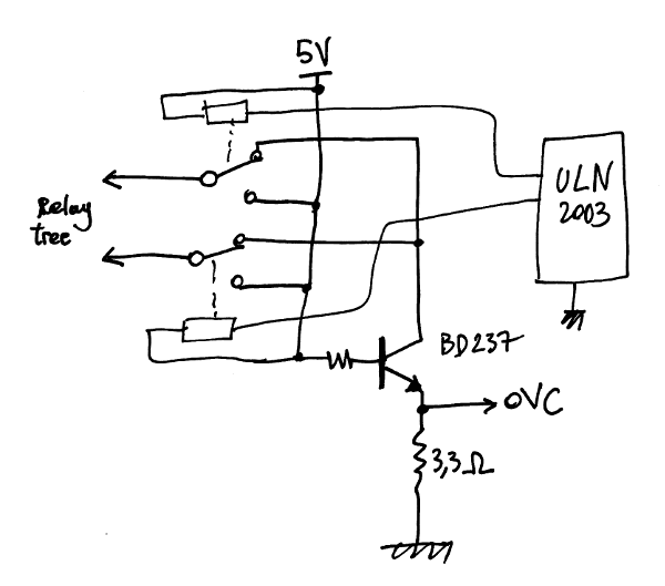
The current for the servos comes from a current generator followed by a polarity selector, which doubles as on/off switch: 2 control signals drive a pair of relays to provide off, forward, backwards, and off (by design, there is no risk of short circuit).
![]()
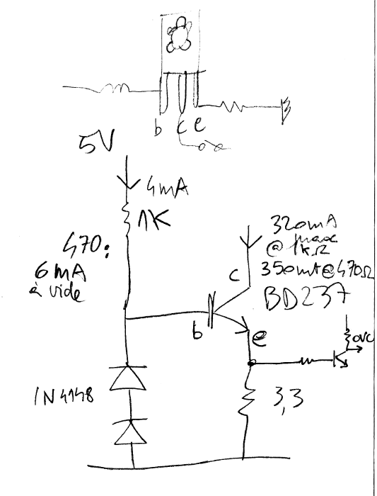
The current limiter is a dumb circuit with a medium power NPN transistor, with the base driven by a chosen current through a simple resistor. There was no point in making a 2-NPN current generator because the drop would not be acceptable. There is some quiescent current (about 6mA) that keeps the DC/DC switch converter loaded.
The emitter is degenerated by a 3.3 Ohm current sense resistor, and the base is shifted by a pair of diodes. The current should be limited to 350mA but no precision is required, as long as it's above the overcurrent sensor threshold value.
![]()
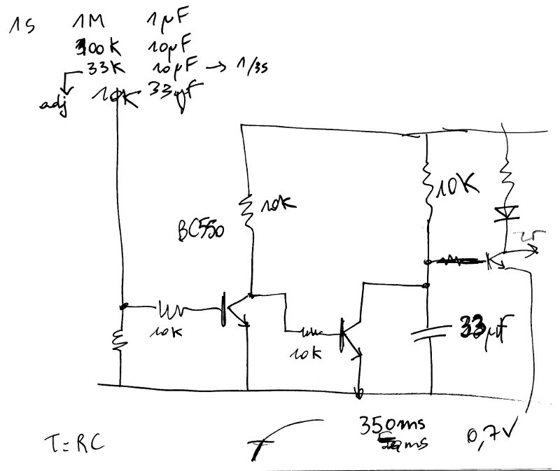
The OVC detection circuit looks like the others, with a cascade of NPN inverters.One of them integrates the signal for some milliseconds because closing the relays creates short pulses that would falsely indicate the end of course. As a previous log mentioned, after I measured the spikes on the 'scope, I managed to calculate the appropriate RC values.
On board#2, I added another inverter that messes a bit with the LED but without severe consequences.
![]()
The circuit should trigger when the current exceeds about 200mA (?) because 3.3×.02=0.66V, which is the threshold voltage for the NPN's base. The next inverter then reshapes the signal and short-circuits the capacitor.
In practice, there might be some small variations but at least the principle is quite simple. I used a lot of "tricks" I learned and explored these last years, including my extensive use of BC550 and BC559 ;-)I decided early against using too much programming and code, this makes the electronics a bit more complex but it's overall more reliable and still easy to repair. The software has relatively little to do and barely cares about the hardware (I added the timeout code later yet it works like a charm).
I'm sure others would have used another approach, more "modern" with an Arduino MEGA with many pins to save on the HC154, or driving the servos with a more classic method. The relays might have a limited lifespan as well... But keeping 12 standard servos powered constantly would draw a LOT of current and 80% of the parts are easy to replace. Most importantly: the clicks add a very fun/stressful sound feedback that the players will both love and dread :-)
-
Finished
09/11/2019 at 23:01 • 0 commentsPrototype #2 is working, delivered, installed and working ! Now is the time for preservation : I must save all the notes and diagrams I have created during the development, not just for your awe and viewing pleasure, but also to help if I ever have to repair/fix/check/adapt the crazy BMOW...
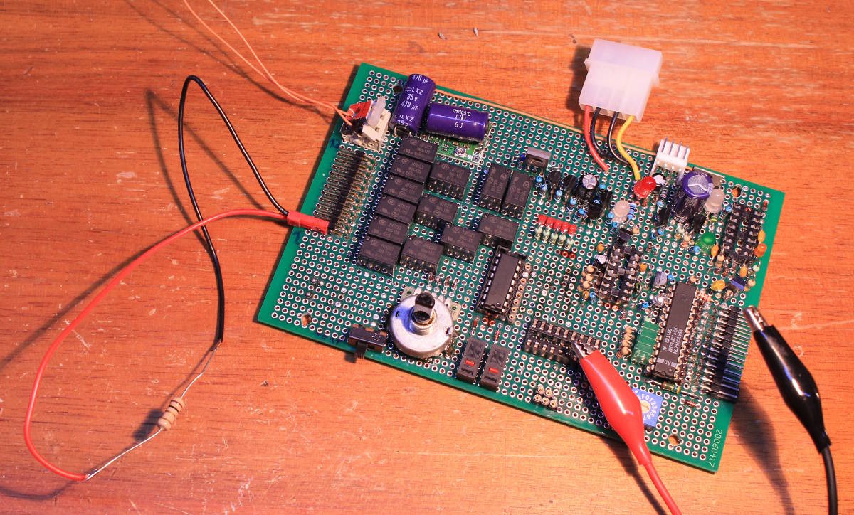
Board#2 is not identical and has a gotcha or two but it works, here I am testing the overcurrent detection circuit to check the logic levels, so the PIC has no ambiguous reading.
I might have damaged the current limiter with the low resistance but the bug disappeared later, I don't know why...
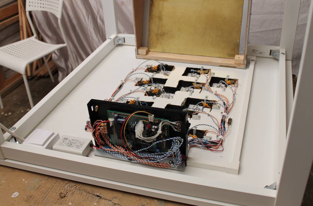
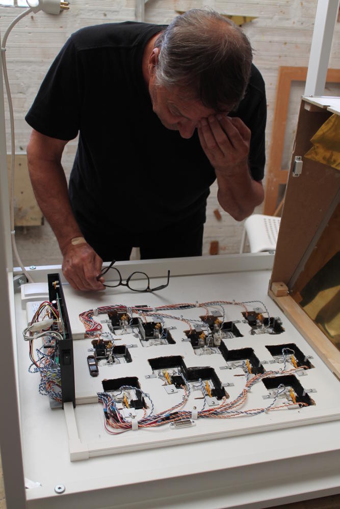
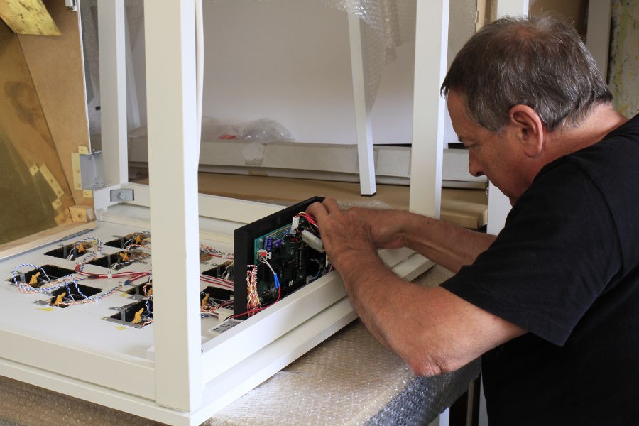
The board is fitted under the table, close to the 12V power supply. This version uses all the 12 channels !
Bob has a few mechanical kinks to iron out but overall the system works like a charm ! Not a surprise when you've been developing something for more than a year ;-)
(sorry for the mostly fuzzy video)
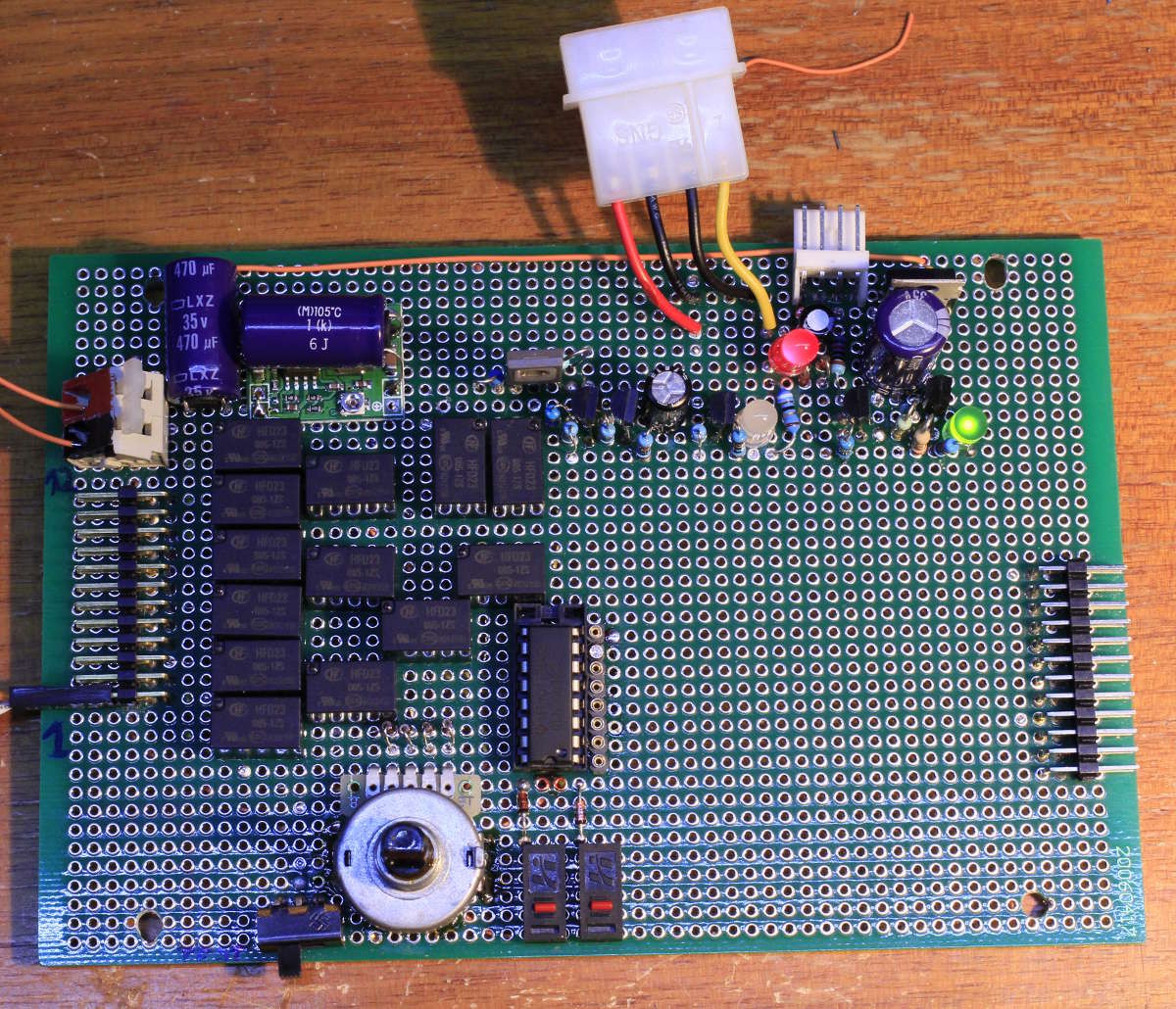
One thing I got right this time : the "difficulty" selector is a rotary hex encoder. The values are accurate, if you select "1" then only one trap is scanned at each turn, and if you select F, all the traps are scanned. It's better than the DIL switches of board#1 but you need a screwdriver.One thing I messed this time : I added a 4th inverter to clean up the levels of the overcurrent sensor and it's tied to the LED... But the LED is high side and I put a NPN transistor through a 10K base resistor, which dumps enough current through the base that the LED stays turned on (lightly). I totally forgot that I added a PNP inverter that removes this problem ! (but "it still works").
Due to the differences with inverters, I had to modify the source code of the 818, complement some levels and I even added a timeout in case of problem with servos (broken, disconnected...) which would block/freeze board#1 in an endless loop (I know, it was lazy, but I was in a hurry). I just uploaded their source code, "just in case I might need it one day".
-
First prototype working !
05/23/2019 at 00:30 • 0 commentsVoilà !
So the whole thing works (at least one of the two prototypes) but I have to admit that I had to "cheat" because after many difficulties with a lousy design, I finally caved and added a PIC16F818... It simplifies many things but creates its own problems.
But it works.
One conclusion is : there is no simple or easy TTL/SSI/MSI chip that helps with building a decent Finite State Machine or a simple automaton. The MC14500B would require several companion chips, including some sort of PROM, which would be overkill for a simple design.
Overall, I see now why microcontrollers have emerged and are a market by themselves. Yet I wish there was a simpler, smaller solution for the trivial functions...
-
Power Supply redesign (20190331)
04/14/2019 at 22:02 • 0 commentsMy initial idea was simple, simplistic and optimistic... I had to change everything and here is the result after I rewired the power supplies :
At first I wanted to power everything from a single 5V source : motor, relays, logic. I realised that they had very different requirements and I had to split the rails, starting from a single 12V input:
- The relays are powered from a DC/DC module
- The DC/DC also powers the motor through a crude current limiter (2 diodes, a resistor and a BD237 NPN transistor with gain around 100) to keep the peak under 400mA
- A separate 7805 provides some tens of mA to the logic
The whole circuit should be more stable and hence predictable... Right ?
-
More progress
04/13/2019 at 22:51 • 0 commentsAfter I redesigned the power supplies (the system can be powered from 12Vdc) and added a current limiter to the motor supply, the design shifts to digital (more or less). I added a 4-bits counter (74HC193 inherited from the #Discrete YASEP project), and a detector for the timer, based on a plain 74HC04. That's where things got really funky, because I built 1) an oscillator 2) a flip-flop 3) a level corrector, just with this 6×inverters chip.
I try to keep my schematics up to date and I should scan them but I use many transistors, diodes, capacitors and resistors to get things done. I have chosen the "discrete parts" route, because I don't want to write a single line of code. It's both ugly and beautiful, from all the LEDs I have sprinkled all over the board to show the operation of the system...
The schematics need some cleanup before I publish them...
-
first tests with the checkerboard
03/08/2019 at 22:14 • 0 commentsNow do you see what I mean ? :-)
-
Connecting the timer
03/04/2019 at 00:47 • 0 commentsThe "user interface" to the "trap chess" board is (beyond a "start" switch) the classic chess dual-timer that each player taps to record the elapsed decision time.
Bob got a cheap but nice looking timer that I reverse-engineered to get to the useful signals, mainly the top switch, which triggers my machinery when it changes state.
First, the timer operates on a single 1.5V AA battery. There is no point in having it installed inside the timer so I power the timer with a ... "shunt regulator". 1.5V is more or less the drop of 2 silicon diodes so here we go : 2× 1N4148 in series, driven by the main 5V supply. Now, usually, you use a resistor to limit the current, but I also used an old red LED in series, to show that the circuit is powered.
The timer draws very very little current but the diodes need to pass quite a lot of current in order to get a suitable drop. The resistor in series with the LED sets the current at around 10mA, and most of it is lost.
The LED also acts as a reverse-blocking diode for when the voltage drops (due to electromechanical activity). A capacitor (100µF) keeps some charge during the transients. Actually, the diodes' leakage and the timer's consumption are so low that the timer won't reset by itself... I need to really remove the connection with 1.5V for the timer to restart correctly later.
The top switch (lap switch ?) has no physical contact (to avoid wear). A reed magnetic switch does the work though. Now, the switch is not powered on permenently : it's polled during 2ms every 32ms. I could patch a wire that sends a train of pulses when the switch is closed, and no pulses when open.I reused the previous circuit, using 2 × BJT, to filter that low-level signal, but development was not as easy as expected. Using my scopes, I could trace and understand my various mistakes and false assumptions. Now a LED is on when the top switch is in one position :-)
(scanned schematics to follow soon)
-
a not-so-basic current sensor
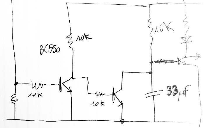
02/18/2019 at 04:20 • 0 commentsI finally solved the problem with the current limit detector. It takes not one but 3 transistors...
![]()
The first transistor detects when the shunt resistor exceeds 0.7V.
The second one short-circuits a 33µF capacitor to ground. When the current exceeds 200mA, the capacitor charges slowly.
The 3rd transistor is another "detector" that turns the LED on when the capacitor reaches 0.7V (it gives a nice level instead of an analog value).
The trick was to determine the RC constant... but back-of-the-envelope estimates worked well on the first try !
The ULN2003A is also wired so the relays can be driven by weak CMOS signals.
-
More work
02/12/2019 at 00:39 • 0 commentsBoard #2 is built and I added more switches to control the current. This makes 6 control signals with fanouts 4, 3, 3, 1, 1, 1. I'll have to wire the ULN2003s...
Now the problem is to detect the end of course through the current in the motor, which is measured by a 3.3 Ohms shunt resistor connected to the base of a transistor. The oscilloscope shows that the generated signal is far from the one I expected... End of course should be set after 50ms of "overcurrent" but should be reset as soon as the current drops under the 0.2A. I try to do a discrete version but it's not as easy as I thought.
-
Power distribution
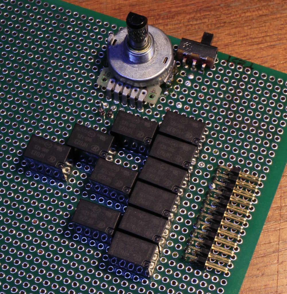
01/21/2019 at 02:42 • 2 commentsI finally decided to use relays to distribute the power to one selected servo.
The path of the power goes through an unbalanced binary tree, made of parallel 8-tree and 4-tree, with a control vector of [1, 2, 4, 4] (total is 11, which is 12-1 as expected).
The relays have a 160 ohms coil, or 32mA @ 5V. The driving requirements for the tree are 32, 64, 128, 128 mA. This is well within the range of a ULN2003 and the total draw (worst case) is about 0.35A.
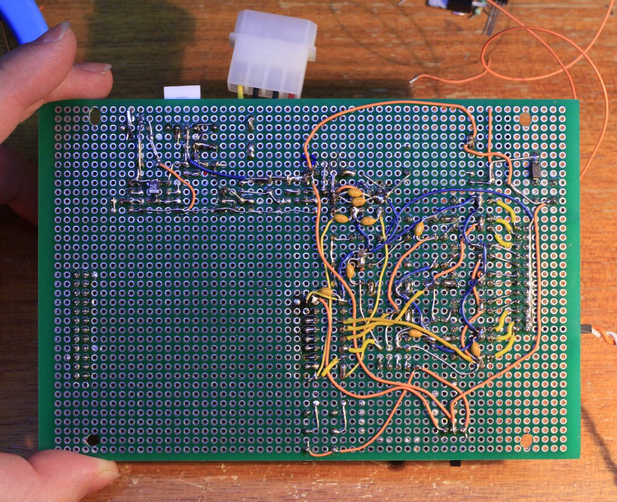
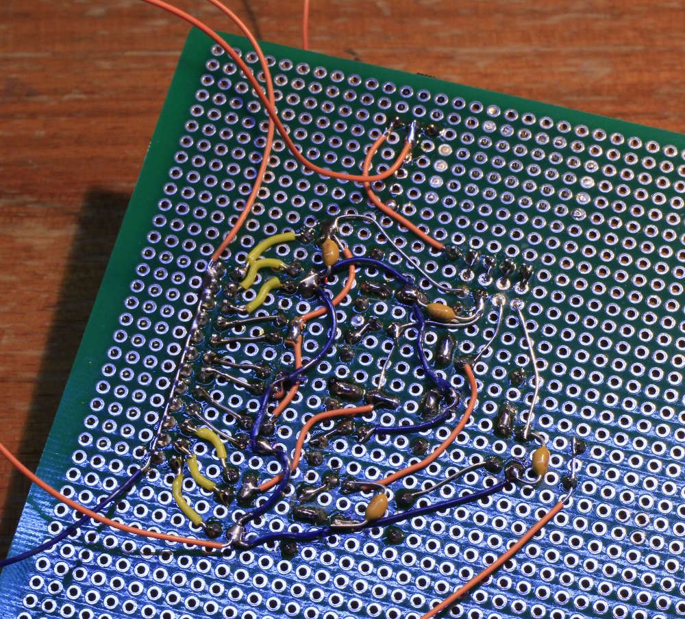
The reverse side is the usual mess:
The 16-positions knob selects one of the 12 outputs, 4 outputs have a duplicate code. I can test the behaviour by hand and the manual control is really helpful during prototyping and later for installation and troubleshooting.
The hex encoder must be disabled during normal operation, which is selected by a small slider switch. This requires anti-feedback diodes on the knob's inputs, hence an increase of the power voltage.
Oh and of course, there is a lot of work to do because now, the servo's motor must be wired directly (the control PCB must be removed). But for now I must focus on controlling the current's direction and detecting the increase of current when the servo has reached its limits. Hint: a 3.3 Ohm resistor develops a potential less than 0.7V when the servo operates normally.
Trap chess
My neighbour creates totally insane chess boards. He needs my electronics skills for this one...
 Yann Guidon / YGDES