Tiny Snowflake
Introduction
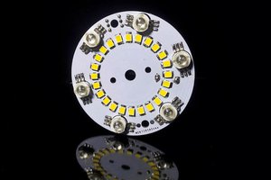
The Tiny Snowflake is a PCB shaped like a snow flake with 19 LEDs. The LEDS are independently controlled by an ATTINY 13 using charlieplexing. Code is uploaded to the device with AVR dude using a Bus Pirate, a AVRisp mk II or similar. It is not Arduino compatible.
Theory
Soldering The Snowflake
Materials
- 5 110 Ohm resistors
- 1 0.1 uF capacitor
- 19 LEDs
- 1 ATtiny13A
- 5v power source (USB, batteries, etc.)
To solder the snowflake follow these steps:


- Solder on all 19 LEDs paying attention to the LED orientation on the silkscreen.
- The center LED is the only one that is not paired so it is very important that it is in the correct orientation. For the rest it is ok to have them all inverse (or just the spokes or just the ring) because this is charlieplexed so these 18 LEDs are in groups of 9 opposing pairs.
- Solder the capacitor onto the PCB.
- Solder the ATtiny13A onto the PCB.
- Solder the Resistors onto the PCB.
- Solder the power cable onto the PCB.
- (Optional) Chain them together by soldering cables onto each other.
Uploading Code
- Code comes pre-uploaded to the ATtiny. The source can be found on github.
Whats Inside the PCB?

This is the schematic of the PCB, showing how all the components are connected.

This is a transparent view of the PCB. Green lines are wires on one side and red lines are wires on the other side of the PCB. The text that will be printed on the board is in magenta on one side and teal on the other. The yellow line is the edge of the board. The gold circles are drilled through the board and have copper on both sides.
How I Made the Gerbers

 SAYANTAN PAL
 ndGarage
 Sagar 001
 Erik Bosman
Nice work. I especially liked your video describing Charlieplexing.