 Amos
AmosWhen I started this project, it was simply a university assignment. I had no thoughts of taking it any further than just enough to get a decent grade. However, as I started preparing prototypes and experimenting with different options I realised that there was some serious potential in this concept. This could form the basis of an interesting way of teaching kids how to program in a very tactile manner. I was lucky in a way, that early in the prototyping stage I realised that the mini breadboards I had were almost the perfect size for the modules. And by "almost the perfect size", I mean they were exactly one row of holes larger than I needed. (Notice the empty row of holes between the Pro Mini and the four in/out pins.)
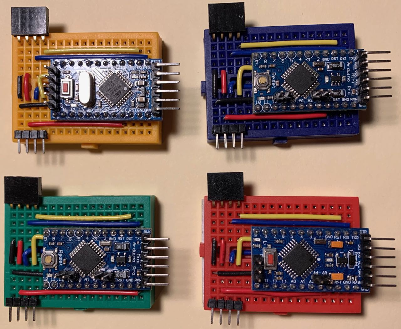
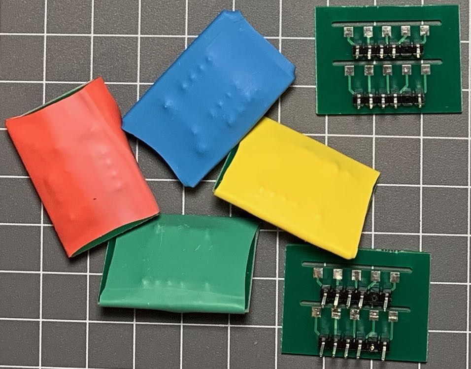
The perfect sizing immediately introduced the idea of using colour to distinguish the programming blocks. The mini breadboards I had came in six different colours - yellow, blue, green, red, white and black.For my prototype I chose yellow, blue, green, and red as variables, white for output and black for "end program". (I also used slightly longer breadboards for loop/end loop as I needed some extra rows to "indent" the code blocks.)
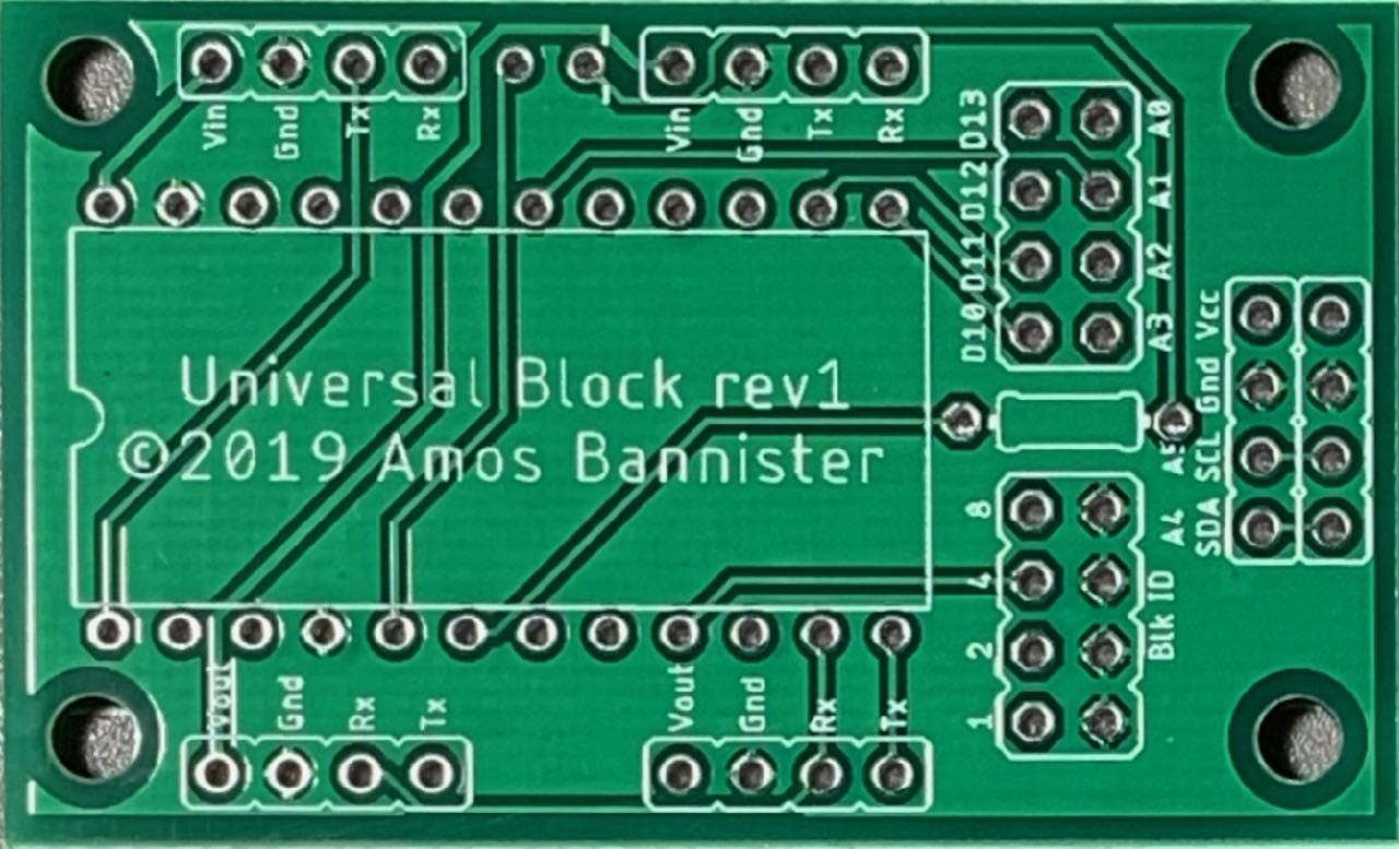
I liked the idea of colour-coded blocks, although using distinct colour blocks for each variable is a little hinky, but it worked well enough for the prototype - I am now considering having a single variable assignment block that takes a dongle to indicate which variable it is modifying. When I made my first batch of PCBs for this project (one problem with the breadboard prototypes was the four pin male/female headers are too easy to rip out of the breadboard) I had to (temporarily) ditch the idea of colour-coded boards. Instead, I planned to eventually create colourful cases for the blocks. JLCPCB (who I used for the PCB fab) do offer coloured soldermasks, but the cost was prohibitive for my meagre budget - effectively doubling or tripling the cost of the PCBs just for choosing colours other than green. Instead I chose plain green and to further reduce costs I made my boards multi-purpose. The boards have a socket for an Arduino Pro Mini, two sets of input pins at the top so you can choose to "outdent" code (for example, an ELSE, or END LOOP block), a corresponding pair of output pins at the bottom to optionally "indent" code (LOOP or IF blocks), a set of block ID jumpers to set the block type, I2C output pins at the right and jumpers for any spare GPIO pins "just in case".
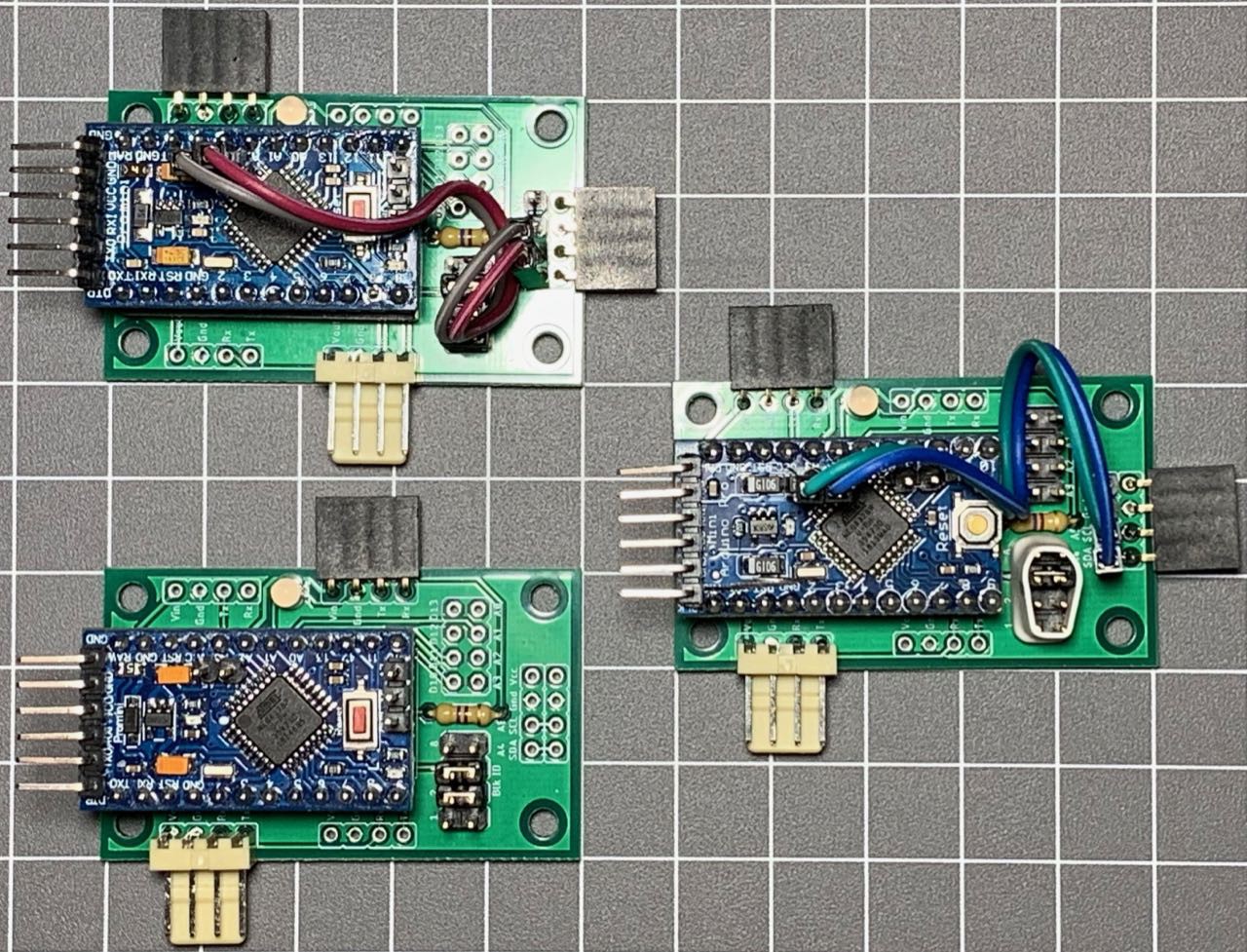
Adopting this approach has allowed me to drastically reduce the costs of the PCBs - one design can be used for almost any block type. However, while I only need a single PCB design for the blocks, I need ancillary modules for values, expressions and other block-type-specific functions. As I design later revisions of the PCBs, I am moving towards having distinct designs for specific types of block. Variable assignment, IF and LOOP blocks all require a variable and/or expression - for these blocks it might be best to build-in the initial value component and then allow the addition of an expression module to build up more complex expressions. I have started down this path and while I lose the "universality" of the blocks, it allows me to think about custom code for specific module types and offers some other advantages. I have a set of PCBs designed along these principles and I do think this is the right path to take moving forward. The block below has an integrated MCP23008 and headers to plug a value or variable dongle into. (I realised after I had soldered up this batch that I didn't need to MCP23008 - I could have used the broken out GPIO pins A0-A3 and D10-D13 instead - doh!)

My next step will be to remove the Pro Mini and use either an Atmega328PB (this variant has two UARTS!) or an ATTiny841 (again - TWO UARTS!) soldered directly on the board. Removing the universality (or limiting it to a degree) and using custom firmware for each block type (so I can remove the Blk ID jumpers) would allow me to reduce the size and complexity of the boards. Of course, it also means more different types of board, which will increase the PCB fab cost, but I think I have come to terms with that idea now.
Which, in a roundabout and meandering way (as is my wont) beings me back tot he thought of coloured PCBs. JLCPCB has just removed the extra cost for coloured PCBs, so a batch of 10 boards is now $2USD for the first design ($5 for subsequent designs in the same batch) in any colour (green, red, yellow, blue, white or black - the same colours as my mini breadboards). Maybe I won't get the program block boards in too many different colours, but I could definitely get some variable dongles in the different colours.
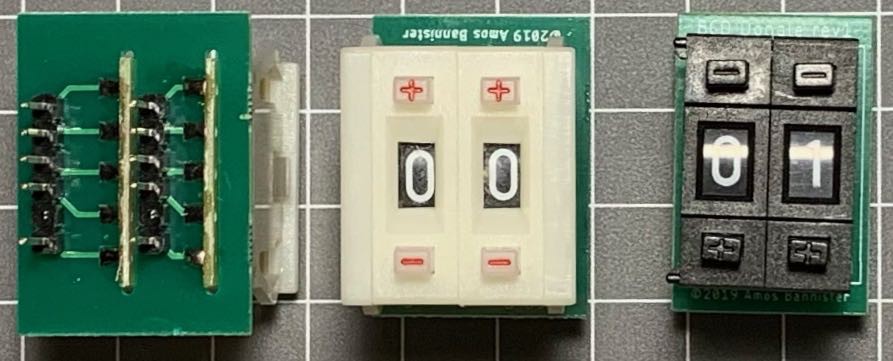
Did I mention my variable and value dongles yet? I have been using some BCD thumbwheels for numeric constants and have a small PCB to mount a pair of wheels so they can be plugged into a value block (or the combined board above) and read via a GPIO port extender. I think they are quite nifty, if a little expensive to source. To represent variables, I am currently using the same PCB with some jumpers soldered to hard-code a value (10 or greater, so it is easily recognised as being different to a regular decimal digit) and then use heatshrink to identify different variables. This scheme works quite well, but I am considering dropping the thumbwheels and use a modified dongle PCB with jumpers for digits from 0 to 9. Not as neat as the thumbwheels, but a darn sight cheaper. ;^) I could very easily get a set of dongle PCBs in each colour and avoid the ugly heatshrink...
So, I guess I need to make my mind up whether to get some coloured block PCBs or just the coloured variable dongles. If I do opt for coloured blocks, which colours for which block types? How many unique block designs will I need? Will the ATTiny841 work for this project, or will I need to extra memory/pins of the 328PB? And finally, how will I pay for all these new PCBs? Any want to sponsor a university student making pointless electronics? ;^)
Discussions
Become a Hackaday.io Member
Create an account to leave a comment. Already have an account? Log In.
I've been thinking about what my actual needs for the next revision boards will be. I am reasonably settled on having two main block designs - one with a value and one without. The block with a value can be used for variable assignment, if statements, loops, output, etc. Blocks without a value can be used for ELSE/END IF blocks, END LOOP, BREAK and END PROGRAM. I am comfortable with having two in and out ports, so I can reconfigure the blocks for indenting/outdenting statements - that seems to work well in my initial prototypes. I am also reasonably comfortable ditching the broken-out GPIO pins - if I have a specific need to break out extra pins (remember, I2C is available on the side port) I can create a custom board.
The block ID jumpers I am not so sure of. If I am happy maintaining a separate code base for each block type, I won't need a block ID on the PCB. However, the block ID jumpers do provide for a handy visual identifier of the block's purpose. If I switch to coloured PCBs, the block ID's visual use is diminished, so I am happy for the jumpers to go in that case. If I maintain a separate code base for each block type, that increases the burden of keeping the code up to date. I can minimise the risks here by using libraries to abstract out common functions, so will it be such a big issue?
Time for more pondering... ;^)
Are you sure? yes | no
Bear in mind that colours will disadvantage colour-blind students, so have other characteristics to distinguish the boards.
Are you sure? yes | no
Yep. The final product will be housed in cases that have other features than colour - different shapes, and maybe even different materials to give an identifiable tactile feel. I will be working with HCI people down the track to make sure this is accessible to a wide variety of people. ;^)
Are you sure? yes | no