 Amos
AmosFirst up, an apology for the lack of updates since I received my last batch of PCBs. There have been a few things going on in my life that I am not willing to discuss here, but it has been a rather trying time. I have been focussing on my family and my studies (in that order) and all of my projects have taken somewhat of a backseat. I'm slowing getting back into the swing of things...
Secondly, another apology is due. I had recorded the unboxing of my PCBs and an initial investigation into the quality, but I am a doofus and the recording was all but unusable. The audio was ruined by a neighbour's intermittent, loud music and the video was affected by a big, clumsy doofus knocking the tripod. After trying to cut around the damage and re-record the voice over, I have decided to give up - it was taking me too long and I am not a videographer. I will try o chop what I have up and reuse some pieces if I can, but the whole unboxing experience was a non-event - sorry about that.
Some Colourful New PCBs...
As you may know, I recently received a batch of PCBs from JLCPCB, who kindly provided them free of charge. This was a great boon, because I am a (mature-age) student, currently living off student payments (Austudy) and as such I don't have a lot of disposable income. JLCPCB recently dropped the price of their coloured PCBs and I thought it would be neat to see how the colours worked for my program blocks. In my original prototype I used coloured breadboards to represent different programming constructs. For example, Red, Green, Blue and Yellow blocks were variables, White blocks were output blocks. Now that colourful PCBs are affordable, I could implement a similar colour scheme again instead of having all green PCBs.
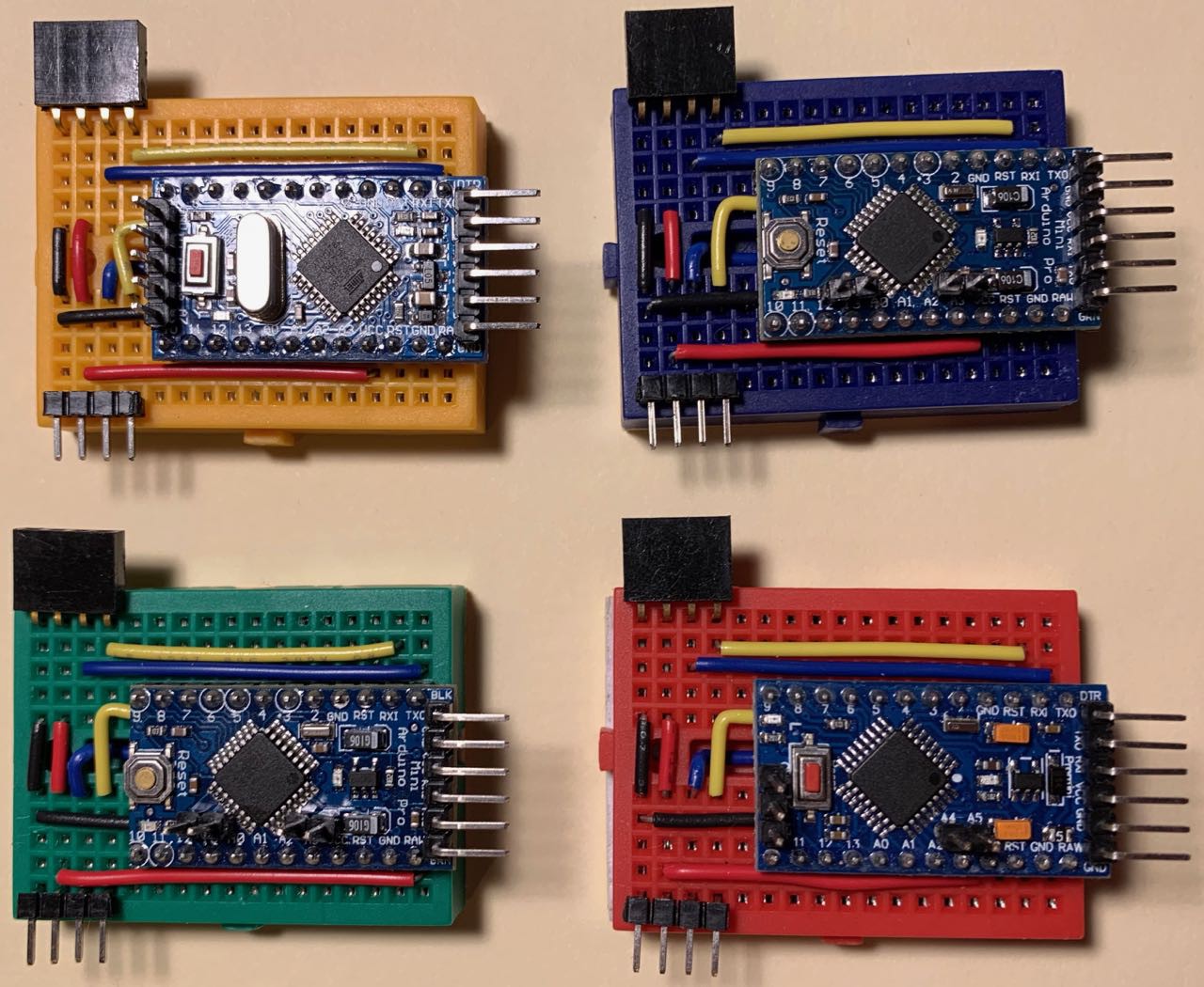
I quite liked those colourful blocks, and have preserved a set of them for posterity. 8^)
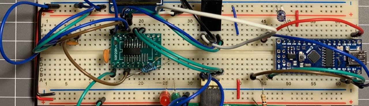
At around the same time I had been experimenting with the ATTiny841 as a replacement for the Arduino Pro Mini clones in my blocks. The '841 is a neat little chip - it has two serial ports, which I can use for the incoming and outgoing connections, and 12 GPIO pins ('though I am using four of those for the serial ports). A bit of ugly breadboarding proved the chip was up to the task, so I decided to take the leap and use the chip in the next iteration of the design.
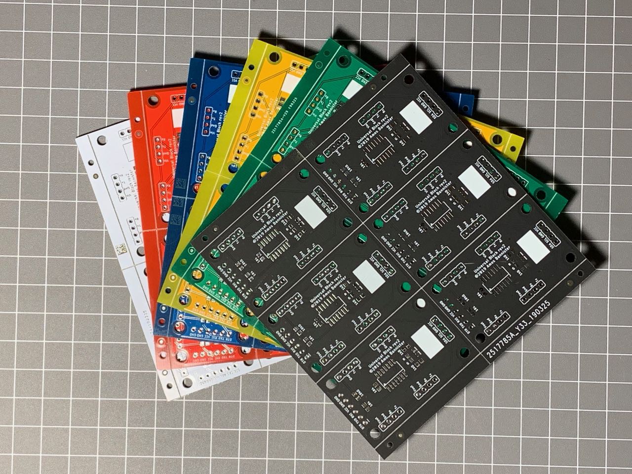
I somewhat cheekily reached out to JLCPCB via Twitter and their representative offered to pay for my next batch of boards, so I went about designing a new PCB layout using the ATTiny841 and placed my order for a small batch of five panels of each colour - Green, Blue, Red, White, Yellow and Black. The new boards would be quite sparse compared to the previous iteration - the '841 is much smaller than an entire Pro Mini and the reduced number of available GPIO pins (out of the 12 available, four are used for 2x serial, 2 for I2C and one for the reset pin, leaving 5 free) meant I had to drop the jumpers for the block id. The lack of block id jumpers means I have to hard-code each block's id, which is not that big a deal IMHO.
Unfortunately (for me) the '841 is only available in an SMD package, so I went the whole hog and used all SMD in the new design. I included an FTDI-compatible programming header on one end of the board so I could easily program the blocks when needed.
Examining the New PCBs
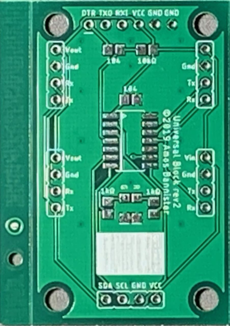
The new panels indeed looked quite sexy!
And breaking the boards apart leaves some very sexy, tiny modules!
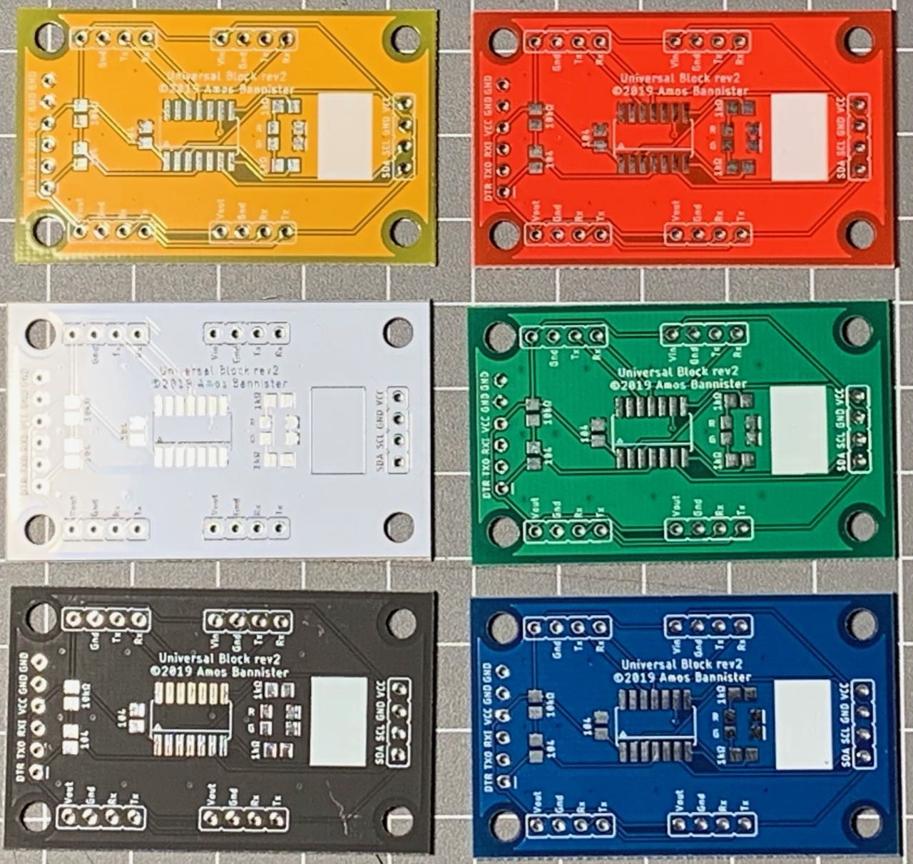
And here is where I discovered my first mistake (thankfully a tiny one) - the Vin label on the first connector was missing. I don't know how that happened, but it is an easy fix.
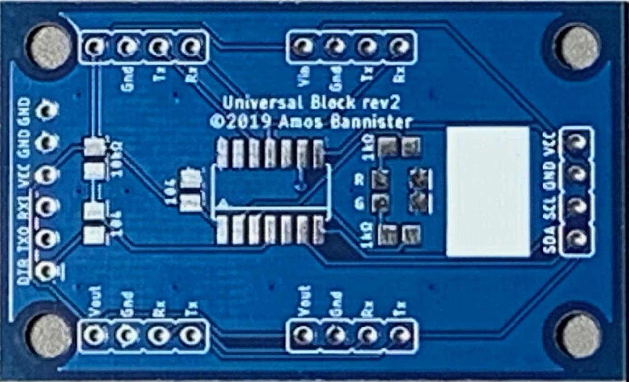
A close inspection of the boards showed them to be very nice. The matte black boards in particular look gorgeous, but all the colours are quite nice. One complaint I have however is the white silkscreen is a little streaky on a small number of the panels. This is really only obvious on the space I put for a block label (the white square at the bottom of the PCB below) and it only seems to affect a small number of boards. Still, it is not ideal. 8^/
A final note on the quality of the coloured PCBs: While the matte black is definitely a very nice looking PCB, I think I might prefer a glossy black to match the look of the other colours. Unfortunately JLCPCB no longer offer glossy black as an option. It would also be nice to have the option of a black silkscreen for the yellow PCBs - the white silkscreen can be a little hard to make out at times, especially for ageing eyes like mine. 8^P
Building the New Boards
Before I document the build procedure, I will state upfront that I have no intention of filming the build - you really don't want to hear a grown man curse the teeny-tiny, little SMT resistors and capacitors. Man those things are small and difficult to wrangle! >_<
The first block I built was a black one - naturally. I had to get the sexiest one built and tested. I didn't use the stencil I had ordered for the first few builds - I just used a syringe to lay down some solder paste and then blasted it with my hot air gun after I placed the components. One minor issue with the black boards showed here - the flux residue looks bad on the matte black, but that should clean up okay with some IPA.
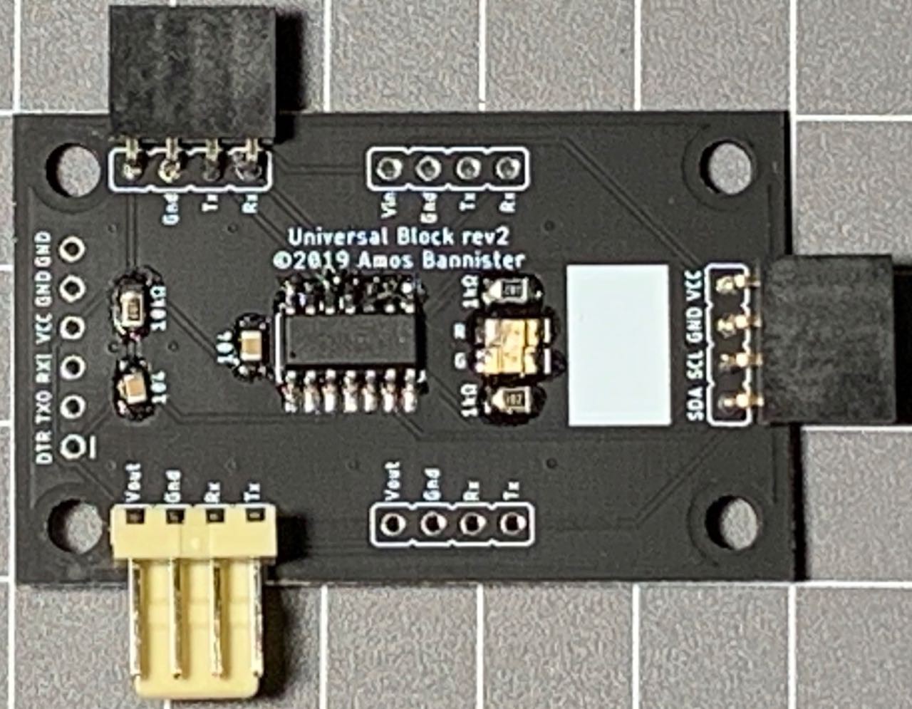
And here was where I discovered two other flaws in my design. 8^(
The first, most obvious flaw was the placement of the LEDs. I am not sure how I managed it, but they are too close. The spacing between the resistors either side was as it should be, but the LEDs had been moved in towards each other. I was able to solder them carefully, but they are a fraction too close for my liking. Checking my Eagle files I must have nudged the two components together at some stage and didn't pick it up in time. I have since fixed the layout in Eagle.
The second flaw is not immediately visible. When I went to program the ATTiny841 it became all too apparent - while I had the FTDI header, I didn't have an ICSP header to flash the bootloader. 8^(
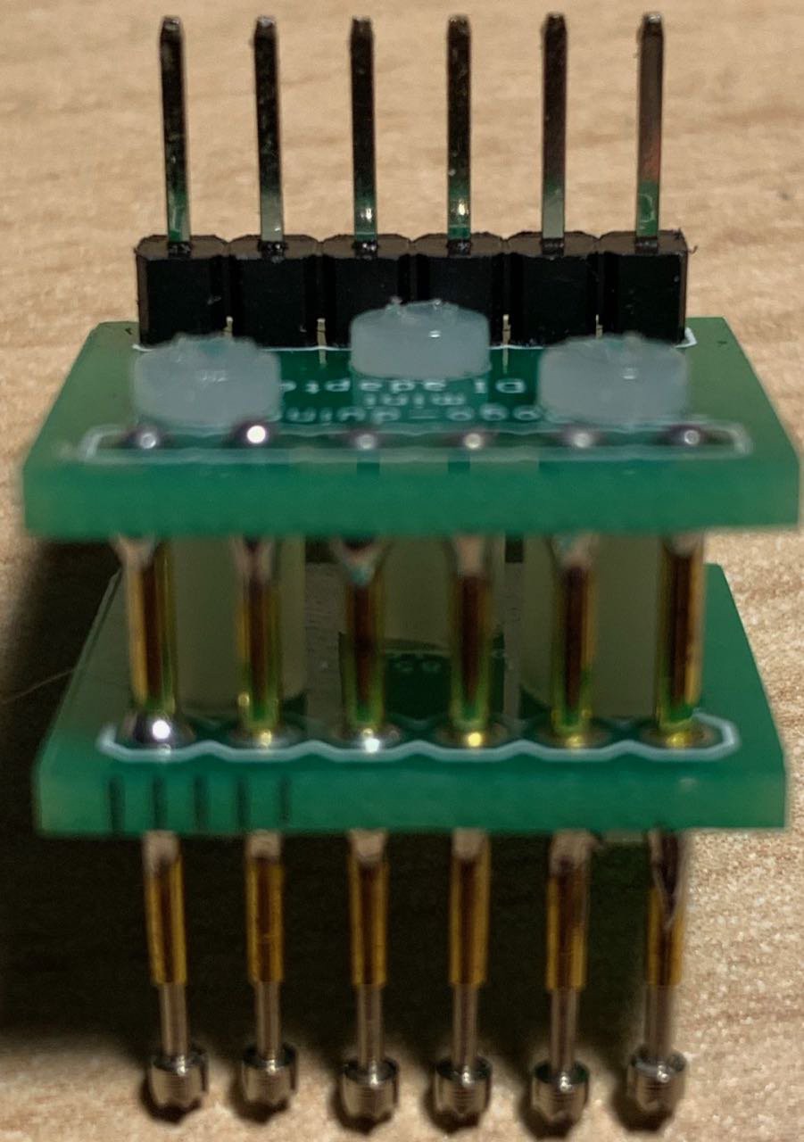
Luckily five of the six pins required for ICSP were available on the pins on the edges of the board, but the Reset pin was not so easy to get to. In the end I was able to hold a jumper onto the reset pin while I flashed the bootloader. It was awkward, but it worked. I am not sure if I will put a full, six-pin ICSP header on the next board, but I will at least break out the Reset pin. Then I will probably make a small programming adapter to plug into the board using the available pins already there.
After flashing the bootloader (Spence Konde's ATTinyCore) I was able to upload my code using an FTDI adapter and a pogo-pin adapter I built.
I was somewhat surprised to see that everything worked as expected! In my excitement I decided to build another board - a white one this time. This time however, all did not go as planned. When it came time to flash the bootloader Avrdude just couldn't see the ATTiny841. I tried reflowing the solder, checked for shorts but nothing worked. I am not sure if the '841 was DOA or if there was another problem with the board. 8^(
Next I built a green board and this one worked perfectly.
After the two successful boards and one failure, I was not entirely confident, but I decided to push ahead and build a batch of boards. I broke out the stencil - it was HUGE! The JLCPCB stencil order form is poorly designed, with a drop-down list of stencil sizes at the top of the form and a "custom size" checkbox down the bottom. I had missed the custom size box and ordered the smallest preset size, which was about A3 size for a 30x50mm board!
I rigged up a stencil holder and started applying paste to four or five boards. I populated the components and hit them with my heat gun. I manually touched up the LEDs to make sure they weren't touching, but all the boards turned out okay. I then made another batch of boards and I ended up with a small collection...
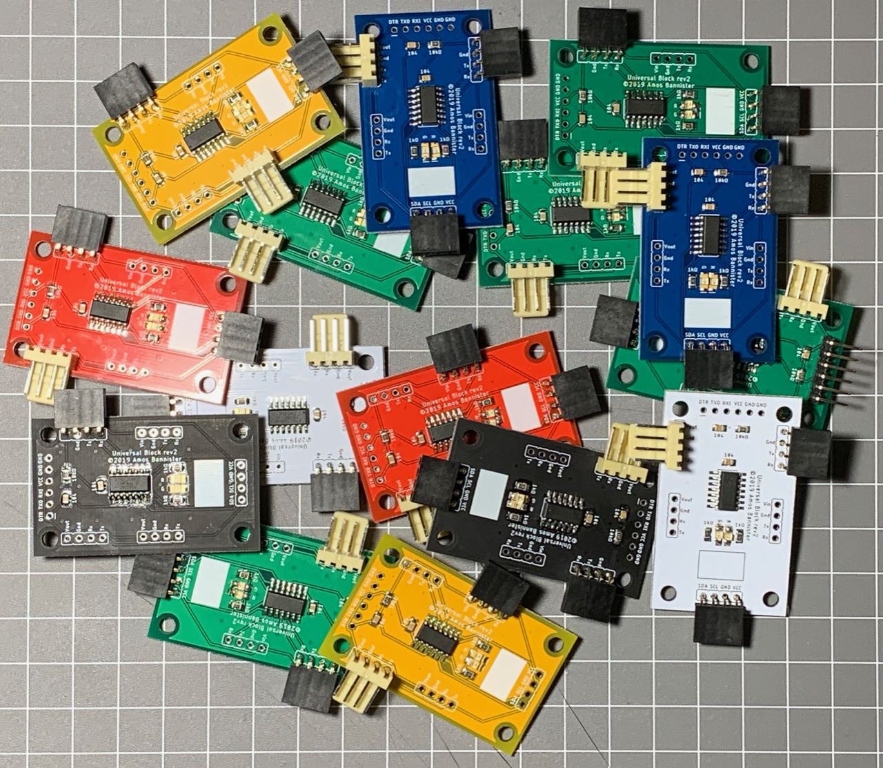
... And they all work, with the exception of the first white board I made. So, I'm pretty happy with the outcome here.
Design Flaws
While I am happy with the overall outcome, there are some flaws with the design that I want to address for the next revision. I will expand on these in a future log entry, but for now here's a brief list:
- Vin silkscreen error
- Need to breakout the Reset pin for ICSP
- Placement of LEDs.
- The LEDs are too close - need to be slightly wider apart
- I haven't really thought about the placement of the LEDs until now, but I think they prolly belong at the front of the board, between the FTDI header and the '841
- I2C pullup resistors should be on this board, instead I have them on the Value/Expression modules
- I should add headers (and an IO expander?) to the board to avoid the need for a separate Value module. Variable, Output, Loop, and If blocks all need a value (and optional expression) to operate, so it would make sense to incorporate the value onto the board.
The colours I am very happy with and I am generally happy with the ATTiny841 (apart from the Reset pin issue). There are some code-related issues I need to debug, but the project is definitely taking shape.
In future logs I will talk about some of these design flaws and how I might fix them, some issues I have encountered with the code and the other boards I received in the same order. Any questions or comments so far would be greatly appreciated. 8^)
Discussions
Become a Hackaday.io Member
Create an account to leave a comment. Already have an account? Log In.