0%
0%
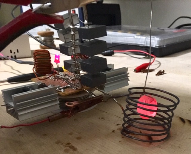
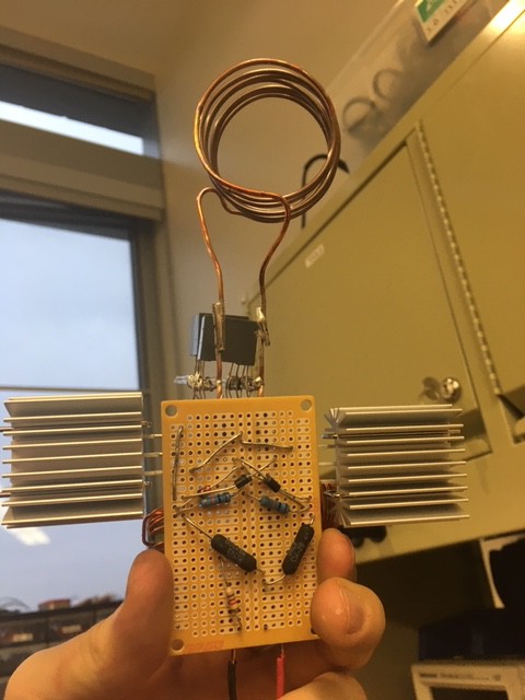
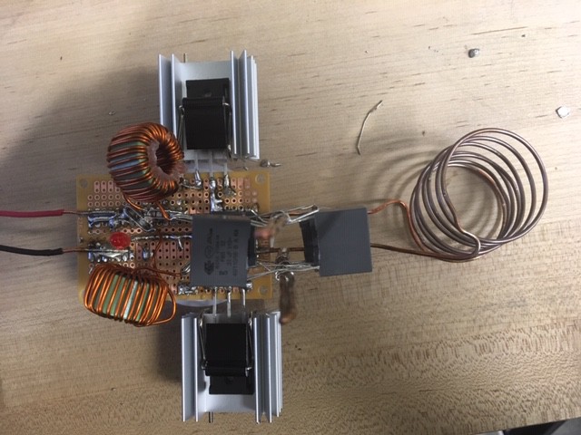
Induction Heater
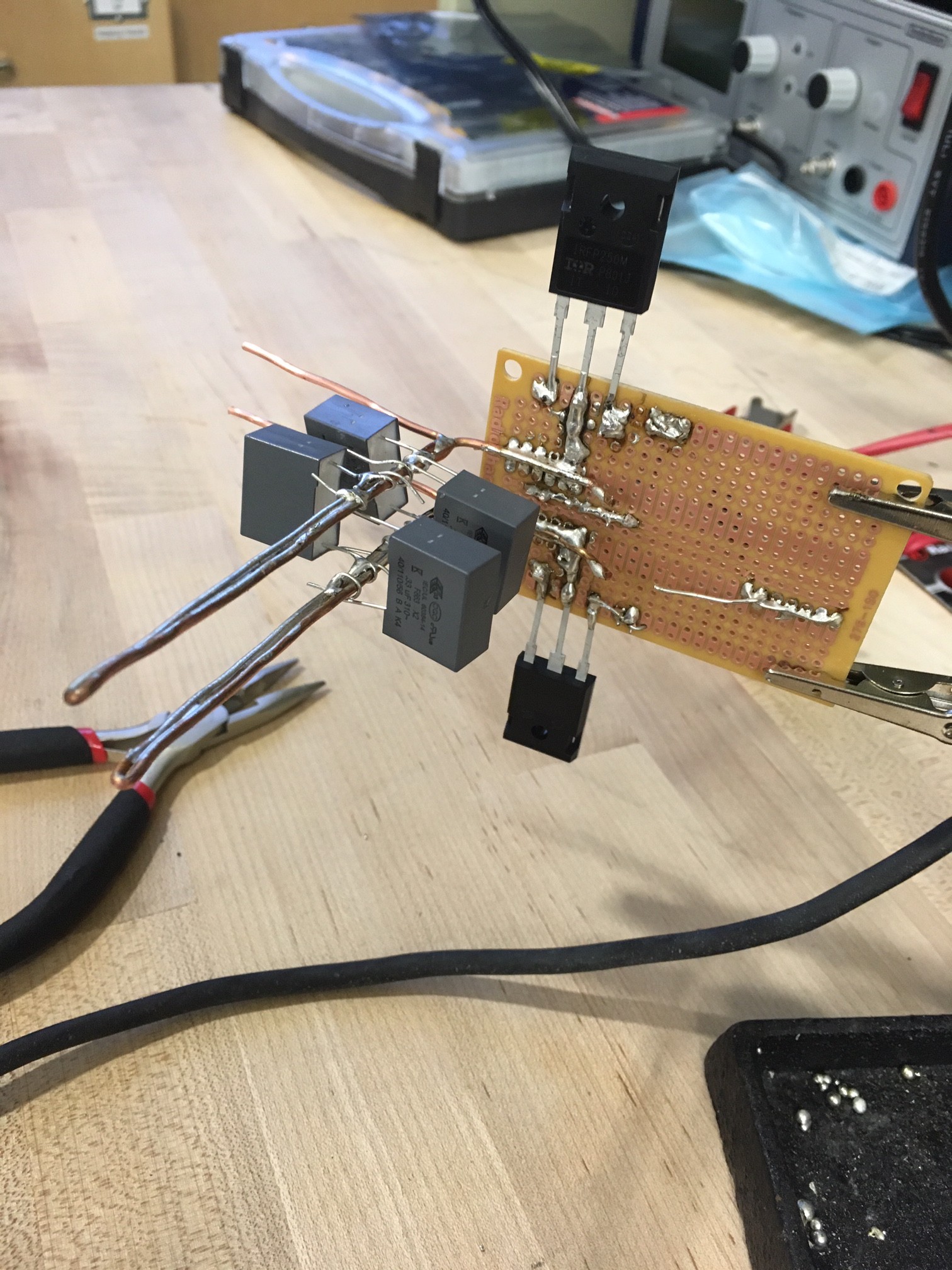
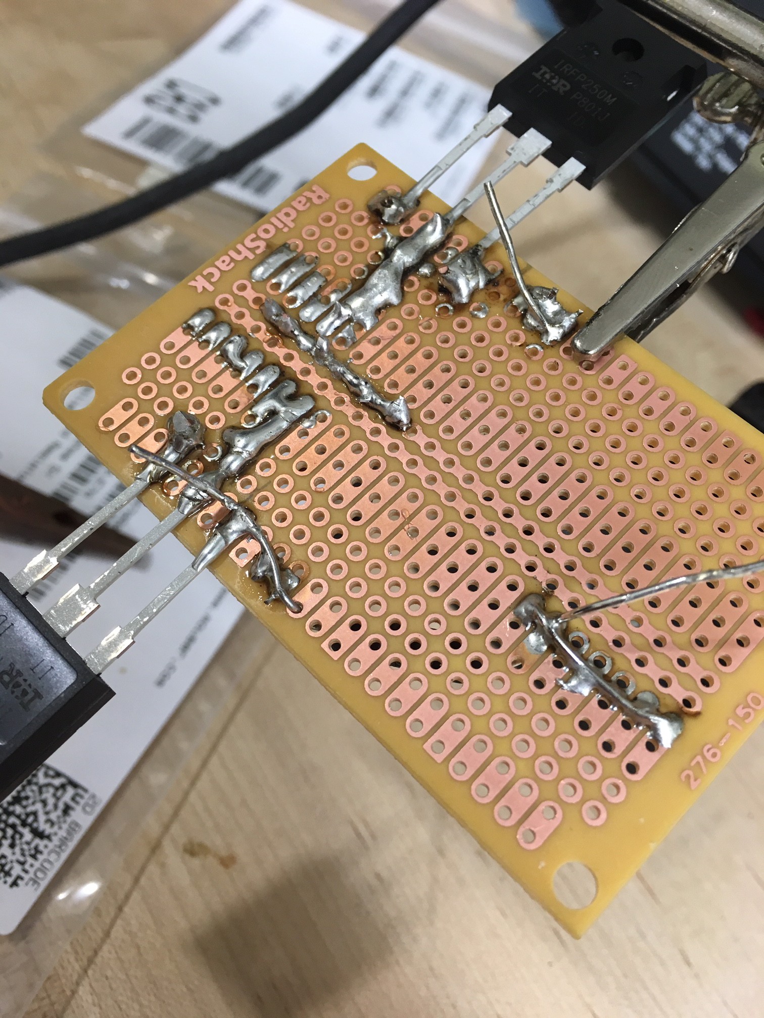
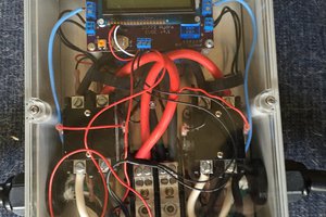
The goal is to build a medium-low power induction heater for a final project for a college-level Analog Electronics class.
 jdunbar360
Become a Hackaday.io member
Already have an account? Log in.
Just one more thing
To make the experience fit your profile, pick a username and tell us what interests you.
Pick an awesome username
hackaday.io/
Your profile's URL: hackaday.io/username. Max 25 alphanumeric characters.
Pick a few interests
Projects that share your interests
People that share your interests
 Nick Sayer
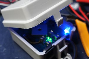
 KingOfKYA(Travis K. )
 Jakob Wulfkind
 Neil Mundt