Close
0%
0%

Jodie and John's Epic Project

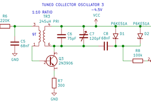
A rain water detector

Similar projects worth following

electronics4.JPG

Original breadboard

JPEG Image - 2.82 MB - 12/20/2018 at 07:34

Preview
Download

electronics1.JPG

Breadboard of our circuit with the diode addition.

JPEG Image - 2.75 MB - 12/20/2018 at 07:34

Preview
Download

electronics3.JPG

Different scaling of voltage over the buzzer.

JPEG Image - 1.96 MB - 12/20/2018 at 07:34

Preview
Download

electronics2.JPG

Voltage over the buzzer as square waves.

JPEG Image - 1.98 MB - 12/20/2018 at 07:34

Preview
Download

  • Day 7

    Jodie McLennan12/20/2018 at 06:00 0 comments

    We finished soldering our circuit elements to the PC board and tested the circuit, making sure that we had wired it up correctly and that it operated when the leads were placed in water. When we did this, we found something very interesting - not only did the buzzer produce noise at a higher pitch and frequency, it also activated regardless of whether or not the probes were inserted in water. We decided to determine the cause of this phenomenon by replicating the soldered circuit on the breadboard using equivalent parts to determine the cause of this issue. We found that in order for the circuit to work the way we anticipated, we needed to relocate the source of the switch in order to produce an output signal.,

  • Day 6

    Jodie McLennan12/18/2018 at 03:08 0 comments

    We started to solder elements of our circuit to printed circuit board. We started by creating a hand-drawn diagram of where we were anticipating placing the various elements in our circuit, placing the buzzer in its location first (because it is the largest element in our circuit). We then placed the remainder of our circuit elements in the drawing, anticipating both the spatial requirements and orientation necessary to building a compact, operational circuit. After doing the initial diagramming, we soldered on our 51K, 22K, and one of our 10K resistors. We also soldered in an IC socket for the op-amp so that we wouldn't need to risk burning it out. These were followed by a jumper wire running from pin 3 of the op-amp socket to ground and then the sixteen 1N4148 diodes in series with each other and in series after the 10K resistor as it delivers current and voltage to the trigger pin of the 555 timer. Our next step is to finish soldering everything and ensuring that it works once everything is attached to the PC board.

  • Day 5

    Jodie McLennan12/16/2018 at 04:50 0 comments

    Today was spent further investigating why the buzzer didn't sound for any potentials higher than 3.55 V. Our first step involved rearranging the circuit on our breadboard so that we could utilize more of the available space, making debugging easier as we would be able to look at individual sections of our circuit rather than attempting to fix something hidden amongst a tangle of wires. We also changed the op-amp that we are using (from the LM741CH to the LM741CN). Using the buzzer alone in the output circuit from the timer at this point still doesn't work. However, two significant observations/achievements were made today:

    1) Given that this circuit is designed to detect the presence of water between two leads, we decided to determine if we could introduce a pair of leads between the voltage source and inverting terminal on the op-amp to see if the circuit still works as intended. This was successful.

    2) The voltage from the output pin on the timer across the buzzer is the same voltage as the input. As we have been working on it, we've consistently found that the buzzer operates when the voltage across the entire circuit has been 3.55 V. Thus, we decided to add a set of in-series diodes before the timer so as to drop the voltage across the timer to 3.55 V by the time current reaches it. After some trial and error, we found that sixteen 1N4148 diodes were enough to produce a sufficient voltage drop (we plan on using a 9 V battery as our power source, so this was determined by running 9 V into the breadboard using the NI Elvis application on the laptop).

    As a result of these two changes, along with the further observations, troubleshooting, and modifications, the buzzer produces an audible, consistent noise without the need for external "persuasion" (pushing leads and intermediate circuit elements around to produce the expected result of noise).

    Because of this, our next step is to solder the circuit elements and lead connections to PC board and attempt to replicate the results that we have observed to date.

  • Day 4

    Jodie McLennan12/14/2018 at 21:38 1 comment

    We spent more time today examining our circuit, looking for the potential source of why our signal (measured via the Tektronix oscilloscope) was not what we anticipated nor what Multisim argued. We tried three different buzzers/speakers, applying a voltage of 3.55 V each time. We found that the larger the speaker we used, the larger the range of viable potentials that could be applied across the circuit. As we were doing this, we realized that the buzzers/speakers fell silent for higher potentials. This gives us the current indication that at 12 V, the resultant angular frequency through the buzzer (recommended by the design we are using) is too high for the buzzer to produce any sound, as it has a maximum frequency rating of 200 Hz. We will continue to examine the circuit to see if there is something fundamentally wrong with it. A discrepancy that we discovered prior to today but haven't addressed yet is the differing values of the potential drop across the resistor between the output pin of the op-amp and the input pin of the 555 timer. We will examine that in more detail soon.

  • Day 3

    Jodie McLennan12/13/2018 at 22:20 0 comments

    Today we attempted to understand why the buzzer was working for a voltage of 3.55 instead of 12V. We found that the voltage across one the resistor in series with the electrolytic capacitor was different in our circuit than in Multisim. We found that the capacitor in out circuit was allowed to charge all the way up instead of 2/3 of the way that it should when connected in parallel to the timer. The resistor is supposed to drain some of the voltage across the resistor so that the capacitor is not charged up all the way. We also discovered that our buzzer will sound a square waves which is why it need the timer to produce the waves. But the timer only produces square waves at a Vcc of 3.55V. We are not sure why this is and next time we will try switching the timers. 

  • Day 2

    Jodie McLennan12/12/2018 at 21:36 1 comment

    Today we set up the circuit on the breadboard. In Multisim we found that the buzzer was going off with the switch closed. When we tried to test it on the breadboard we found that the buzzer went off at 3.55V instead of the 12V that Multisim and what we had predicted. The 3.55V worked for a buzzer and a speaker. Next time we might add a voltage divider to give only 3.55V to the buzzer for a 9V battery source. We will also try to figure out why the Multisim and our breadboard differ.  

  • Day 1

    Jodie McLennan12/10/2018 at 21:34 0 comments

    Today we set up our circuit in Multisim and were able to verify that current was running through each component. We have received all our components. Next time we will verify that the buzzer will go off in Multisim.   

View all 7 project logs

Enjoy this project?

Share

Discussions

Similar Projects

Does this project spark your interest?

Become a member to follow this project and never miss any updates